

FOXBORO FBM216 HART® Communication Redundant Input Interface Module
FBM216 HART® Communication Redundant Input Interface Module
The FBM216 offers redundant modules for eight input channels, each accepting a 4 to 20mA analog signal
or a digital HART® signal superimposed on a 4 to 20 mA analog signal.
FEATURES
Key features of the FBM216 module are:
Eight analog input channels, each accepting one
of the following inputs:
• Standard 4 to 20 mA analog sensor signal
• Digital HART Frequency Shift Keying (FSK)
signal superimposed on a 4 to 20 mA analog
signal.
Module pair offers redundancy at the FBM level
FSK modem dedicated to each input channel for
bi-directional digital communications with a
HART field device
Analog to digital conversion of each of the 4 to
20 mA input signal from the HART devices
Support for the HART universal commands
necessary to interface the field device with the
I/A Series® system database
Galvanic isolation of the group of 8 input
channels from ground and module logic
Compact, rugged design suitable for enclosure in
Class G3 (harsh) environments
High accuracy achieved by sigma-delta data
conversions for each channel
Termination Assemblies (TAs) for locally or
remotely connecting field wiring to the FBM216
Termination Assemblies for per channel internally
and/or externally loop powered transmitters.
OVERVIEW
The FBM216 HART Communication Redundant
Input Interface Module contains eight group-isolated
input channels. The FBM216 supports any mix of
standard 4 to 20 mA devices and HART devices.
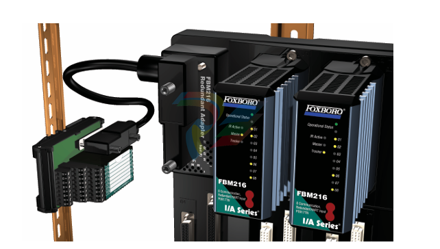
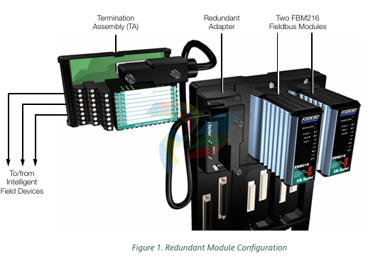
A pair of modules combines to provide redundancy
at the Fieldbus Module (FBM) level, with field inputs
wired to one common termination assembly (see
Figure 1). In this configuration, one FBM216 is the
Master, and the other is the Tracker.
The FBM216 serves as a HART communications field
device host, enabling the I/A Series system to
request and receive two digital messages per second
from each field device. The message pass-through
capability can be used to support HART universal,
common practice, and device-specific commands,
but not the burst communication mode. These
commands are implemented using the Intelligent
Field Device Configurator (IFDC — refer to PSS
21S-8A2 B3 for details).
The FBM216 provides a common isolated power
supply to power all eight channels. Optionally, the
channels can be powered by an external power
supply, in which case a Cable Balun module is
required to prevent channel crosstalk.
HIGH ACCURACY
For high accuracy, the module incorporates a Sigma
Delta converter which can provide new analog input
values for each channel every 100 milliseconds.
COMPACT DESIGN
The FBM216 has a compact design, with a rugged
extruded aluminum exterior for physical protection of
the circuits. Enclosures specially designed for
mounting the FBMs provide various levels of
environmental protection, up to harsh environments
per ISA Standard S71.04
HIGH RELIABILITY
The redundancy of the module pair, coupled with the
high coverage of faults, provides very high
subsystem availability time.
Either module may be replaced without upsetting
field input signals to the other module. A module can
be removed or replaced without removing field
device termination cabling, power, or
communications cabling.
REDUNDANT ANALOG INPUTS
For each input operation, identical reads are sent to
both modules, fully exercising the Fieldbus and the
logic circuitry of each module. Each input channel
accepts an analog sensor input or a self-powered
4 to 20 mA source. Device power from each module
is diode OR’d together in the redundant adapter to
ensure redundant power.
The microprocessor of each module executes the
analog I/O application program, plus security routines
that validate the health of the FBM. Input channel
security is enhanced by redundantly powering the
input current loop from per-channel power supplies in
each module of the pair.
VISUAL INDICATORS
Light-emitting diodes (LEDs) incorporated into the
front of the module provide visual indication of the
module’s operational and redundancy status, and
communication activity on the channels. Two
additional LEDs provide the master or tracker status
of the modules.
FIELDBUS COMMUNICATION
A Fieldbus Communication Module or a Control
Processor interfaces the redundant 2 Mbps module
Fieldbus used by the FBMs. The FBM216 module
accepts communication from either path (A or B) of
the redundant 2 Mbps fieldbus – should one path fail
or be switched at the system level, the module
continues communication over the active path.
The use of an external power supply common to two
or more loops requires a Cable Balun module to
maintain communication signal line balance.
MODULAR BASEPLATE MOUNTING
The module mounts on a modular baseplate which
accommodates up to four or eight FBMs. The
modular baseplate is either DIN rail mounted or rack
mounted, and includes signal connectors for
redundant fieldbus, redundant independent dc
power, and termination cables.
Redundant modules must be lo
CABLE BALUN MODULE
The Cable Balun module is used to maintain digital
communication line balance for HART Transmitter to
FBM loops that are powered from a common
external power supply. This powering effectively
connects one line of each loop together. Without the
Baluns, in each loop so powered, the common
connection at the external power supply, would
cause near end crosstalk at the system end of the
loop wiring cable. Loops using FBM internal power
source do not require Baluns.
The Cable Balun module contains multiple Baluns.
One Balun segment is interconnected in each loop
powered from an external power supply per the
diagram above. There is one Cable Balun module.
Field Device Channels
VERSION SUPPORTED
HART Protocol v6
INTERFACE
8 group-isolated channels
COMMUNICATION TO THE DEVICE
Point-to-point, master/slave, asynchronous, half
duplex, at 1200 baud
ERROR CHECKING
Parity on each byte, and one CRC check byte
SPEED
2 messages per second
FASTEST ALLOWED ECB BLOCK PERIOD
500 msec
MAXIMUM DISTANCE (FBM216 TO FIELD
DEVICE)
Meets HART FSK physical layer specification
HCF_SPEC-54. Revision 8.1 [up to 3030 m
(10000 ft)](1)
COMPLIANCE VOLTAGE
18 V dc minimum at 20.5 mA
CURRENT INPUTS
Sense Resistor
61.9 Ω nominal
Total Input Resistance
280 Ω minimum
Analog Accuracy (Includes Nonlinearity)
± 0.075%(2) of full scale
Temperature Coefficient
50 PPM/°C
Resolution
15 bits
Update Rate
100 ms
Integration Time
500 ms
Common Mode Rejection
>100 db at 50 or 60 Hz
Normal Mode Rejection
>35 db at 50 or 60 Hz
LOOP POWER SUPPLY PROTECTION
Each channel is galvanically group isolated,
current limited, and voltage regulated.
All inputs are limited by their design to less than
30 mA with a single module installed (60 MA
when redundant modules are installed). If the
current limit circuit shorts out, the current is
limited to about 85 mA.
MAXIMUM LOOP RESISTANCE
280 Ω (not including the field device)(3)
FBM INPUT IMPEDANCE
280 Ω minimum
FBM INTERNAL POWER FOR FIELD DEVICE
24 V dc ±10% common power supply for all
channels. Loop load limited to one device per
channel.
ISOLATION
The channels are not galvanically isolated from
each other, but are galvanically isolated (both
optical and transformer isolation) as a group from
ground and module logic. Inputs use an internal
FBM isolated power supply for field power. The
module withstands, without damage, a potential
of 600 V ac applied for one minute between the
group isolated channels and earth (ground).
CAUTION
This does not imply that these channels are
intended for permanent connection to
voltages of these levels. Exceeding the limits
for input voltages, as stated elsewhere in this
specification, violates electrical safety codes
and may expose users to electric shock
FUNCTIONAL SPECIFICATIONS (CONTINUED)
Fieldbus Communication
Communicates with its associated FCM or FCP via
the redundant 2 Mbps module Fieldbus
Power Requirements
INPUT VOLTAGE RANGE (REDUNDANT)
24 V dc ±5%
CONSUMPTION
7 W (maximum)
HEAT DISSIPATION
4 W (maximum)
Regulatory Compliance
ELECTROMAGNETIC COMPATIBILITY (EMC)
European EMC Directive 89/336/EEC
Meets: EN 50081-2 Emission standard
EN 50082-2 Immunity standard
EN 61326 Annex A (Industrial Levels)
CISPR 11. Industrial Scientific and Medical
(ISM) Radio-frequency Equipment -
Electromagnetic Disturbance Characteristics - Limits and Methods of Measurement
Meets Class A Limits
IEC 61000-4-2 ESD Immunity
Contact 4 kV, air 8 kV
IEC 61000-4-3 Radiated Field Immunity
10 V/m at 80 to 1000 MHz
IEC 61000-4-4 Electrical Fast
Transient/Burst Immunity
2 kV on I/O, dc power and communication
lines
IEC 61000-4-5 Surge Immunity
2kV on ac and dc power lines; 1kV on I/O
and communications lines
IEC 61000-4-6 Immunity to Conducted
Disturbances
10 V (rms) at 150 kHz to 80 MHz on I/O,
dc power and communication lines
IEC 61000-4-8 Power Frequency Magnetic
Field Immunity
30 A/m at 50 and 60 Hz
PRODUCT SAFETY
European Low Voltage Directive 73/23/EEC
SAFETY CERTIFICATION (FBM AND CABLE
BALUN)
Underwriters Laboratories (UL) for U.S. and
Canada
UL/UL-C listed as suitable for use in
UL/UL-C listed Class I, Groups A-D;
Division 2; temperature code T4 enclosure
based systems. These modules are also UL
and UL-C listed as associated apparatus for
supplying non-incendive communication
circuits for Class I, Groups A-D hazardous
locations when connected to specified
I/A Series® processor modules as described
in the I/A Series DIN Rail Mounted
Subsystem User’s Guide (B0400FA). Where
power is supplied by the FBM,
communications circuits also meet the
requirements for Class 2 as defined in
Article 725 of the National Electrical Code
(NFPA No.70) and Section 16 of the
Canadian Electrical Code (CSA C22.1).
Conditions for use are as specified in the
I/A Series DIN Rail Mounted Subsystem
User’s Guide (B0400FA).
European Low Voltage Directive 73/23/EEC
and Explosive Atmospheres (ATEX) directive
94/9/EC
CENELEC (DEMKO) certified as EEx nA IIC
T4 for use in CENELEC certified Zone 2
enclosure certified as associated apparatus
for supplying non-incendive field circuits for
Zone 2. Group IIC, potentially explosive
atmospheres when connected to specified
I/A Series processor modules as described
in the I/A Series DIN Rail Mounted
Subsystem User’s Guide (B0400FA). Also,
see Table 1 on page 10.
Calibration Requirements
Calibration of the module or termination assembly is
not required
ENVIRONMENTAL SPECIFICATIONS(4)
Operating
TEMPERATURE
Module-20 to +70°C (-4 to +158°F)
Termination Assembly
PVC-20 to +50°C (-4 to +122°F)
PA-20 to +70°C (-4 to +158°F)
RELATIVE HUMIDITY
5 to 95% (noncondensing)
ALTITUDE-300 to +3.000 m (-1.000 to +10.000 ft)
Storage
TEMPERATURE-40 to +70°C (-40 to +158°F)
RELATIVE HUMIDITY
5 to 95% (noncondensing)
ALTITUDE-300 to +12.000 m (-1.000 to +40.000 ft)
Contamination
Suitable for use in Class G3 (Harsh) environments as
defined in ISA Standard S71.04. based on exposure
testing according to EIA Standard 364-65. Class III.
Vibration
7.5 m/S2 (0.75 g) from 5 to 500 Hz
PHYSICAL SPECIFICATIONS
Mounting
MODULE
FBM216 mounts on a modular baseplate. The
baseplate can be mounted on a DIN rail
(horizontally or vertically), or horizontally on a
19-inch rack using a mounting kit. Refer to
PSS 21H-2W6 B4 for details.
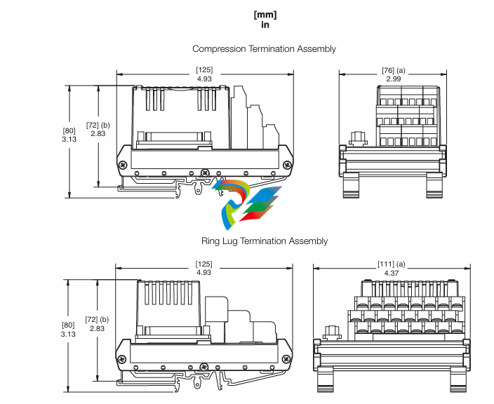
TERMINATION ASSEMBLY
The TA mounts on a DIN rail and accommodates
multiple DIN rail styles including 32 mm (1.26 in)
and 35 mm 1.38 in).
Mass
MODULE
284 g (10 oz) approximate
TERMINATION ASSEMBLY
Compression
181 g (0.40 lb) approximate
Ring Lug
249 g (0.55 lb) approximate
Dimensions – Module
HEIGHT
102 mm (4 in)
114 mm (4.5 in) including mounting lugs
WIDTH
45 mm (1.75 in)
DEPTH
104 mm (4.11 in)
Dimensions – Termination Assembly
See page 11.
Part Numbers
FBM216 MODULE
P0922VV
TERMINATION ASSEMBLIES
See “FUNCTIONAL SPECIFICATIONS –
TERMINATION ASSEMBLIES” on page 9
REDUNDANT ADAPTER
P0917XQ
Termination Cables
CABLE LENGTHS
Up to 30 m (98 ft)
CABLE MATERIALS
Polyurethane or Hypalon®/XLP
TERMINATION CABLE TYPE
Types 1 – See Table 2 on page 10.
CABLE CONNECTION – TA
25-pin male D-subminiature
Construction – Termination Assembly
MATERIAL
Polyvinyl Chloride (PVC), compression
Polyamide (PA), compression
PVC, ring lug
FAMILY GROUP COLOR
Green – communication
TERMINAL BLOCKS
3 tiers, 8 positions
Field Termination Connections
COMPRESSION-TYPE ACCEPTED WIRING
SIZES
Solid/Stranded/AWG
0.2 to 4 mm2/0.2 to 2.5 mm2/24 to 12 AWG
Stranded with Ferrules
0.2 to 2.5 mm2 with or without plastic collar
RING-LUG TYPE ACCEPTED WIRING SIZES
#6 size connectors (0.375 in (9.5 mm))
0.5 to 4 mm2/22 AWG to 12 AWG
TERMINATION ASSEMBLIES AND CABLES
Field input signals connect to the FBM subsystem via
DIN rail mounted Termination Assemblies, which are
electrically passive. TAs for the FBM216 are
available in the following forms:
Compression screw type using Polyvinyl Chloride
(PVC) material
Compression screw type using Polyamide (PA)
material
Ring lug type using PVC material
See the following “FUNCTIONAL SPECIFICATIONS –
TERMINATION ASSEMBLIES” for a list of TAs used
with the FBM216.
The FBM216 provides sufficient loop resistance to
allow use of the HART Hand-Held Terminal, or PC20
Intelligent Field Device Configurator (PSS 2A-1Z3 E).
A removable termination cable connects the DIN rail
mounted TA to the FBM via a field connector on the
baseplate in which the FBM is installed. Termination
cables are available in the following materials:
Polyurethane
Hypalon XLP.
Termination cables are available in a variety of
lengths, up to 30 meters (98 feet), allowing the
Termination Assembly to be mounted in either the
enclosure or in an adjacent enclosure. See Table 2
for a list of termination cables used with the TAs for
the FBM216.
-
Kollmorgen AKM54G-ANC2DB00 servo motor
-
Kollmorgen S200 Series S20350-VTS SERVO DRIVE
-
KOLLMORGEN AKD-P00606-NBCC-I000 SERVO DRIVE
-
Kollmorgen MV65WKS-CE310/22PB Servo Drive Control Module
-
Kollmorgen S20360-VTS-021 Servo Drive
-
KOLLMORGEN CR06550 High-precision digital servo amplifier
-
KOLLMORGEN DBL5N01050-03S-VV0-S40 Phase AC Synchronous Brushless Servo Motor
-
KOLLMORGEN S70301-NANANA-024 SERVO DRIVE
-
Kollmorgen S20360-VTS S200 Series Servo Drive
-
Kollmorgen RBE-03011-A00 Brushless Frameless Servo Motor
-
KOLLMORGEN AKD-T00306-NBAN-0000 INPUT SERVO DRIVE
-
KOLLMORGEN S700 Servo Controller S70302-NANANA
-
Kollmorgen AKD-P00607-NBEC-0000 400/480VAC 4.40KVA Servo Drive.
-
KOLLMORGEN S70102-NANANA SERVO DRIVE
-
KOLLMORGEN AKM21E-ANSNEH02 PM Servo Motor & PRD-AMPE25EB-00 Servo Drive Array
-
KollMorgen SC1R06260 Servo Drive 1.4/2.2 KVA 115230 Vac
-
Kollmorgen AKD-P00306-NBAN-0000 Servo Drive
-
Kollmorgen TTB2-2042-3052-A DC Motor Industrial Drive 5.5A 185 oz/inIntegrated safety
-
KOLLMORGEN SERVOSTAR 610-AS SERVO AMPLIFIER_SERVOSTAR610AS_S61001
-
KOLLMORGEN Seidel 60WKS-CE240/26PB 26A Servo Drive Module Control 60WKS-M240/26
-
KOLLMORGEN PRD-0016400P-10 & PRD-0016600D-30 Axis Control System Modules
-
KOLLMORGEN Seidel DBL5N01700-03S-000-S40 Servo Motor
-
HIRSCHMANN RS30-0802O6O6SDAP RAIL SWITCH
-
Hirschmann RS20-1600M2T1SDAEHH03.1.02 Rail Switch
-
Hirschmann RSPM20-4T14T1EV9HHS999.9.99 Managed Ethernet Switch
-
Hirschmann BELDEN RS40-0009CCCCSDAPHH09.0.14 / RS400009CCCCSDAPHH09014
-
Hirschmann RS40 Rail Switch RS40-0009CCCCSDAE
-
Hirschmann BELDEN RS30-0802T1T1SDAP / RS300802T1T1SDAP Fully Managed Layer 2 Compact Rail Switch
-
Hirschmann BELDEN RS20-0800M2M2SDAUHH / RS200800M2M2SDAUHH
-
Hirschmann EAGLE30-04022O6TT999SCCY9HSE3F Industrial Firewall Router Switch
-
Hirschmann RS20-1600T1T1SDAEHH09.0.14 RS20 Rail Mount Ethernet Switch
-
Hirschmann EAGLE 0200T1T1TDDY90000HHE05.3.03 Industrial Security Router
-
Hirschmann - BELDEN MIPP-AD-1L9P
-
HIRSCHMANN RSPM20-4Z64Z6TV9HHS9 942 106-999 RAIL SAFETY SWITCH
-
HIRSCHMANN FIBEROPTIC MODULE FIP P/N: OZDFIPG3 T
-
HIRSCHMANN RS20-1600M2M2SDAUHH Ethernet rack-mounted switch
-
BELDEN RS20-0400T1T1SDAEHH04.0.01 / RS200400T1T1SDAEHH04001
-
HIRSCHMANN MM2-4FXM3 MICE Media Module
-
Hirschmann RS20-2400T1T1SDAP / RS20-2400T1T1SDAPHH05.0.02
-
GE MLJ1005B010H00C MLJ Digital Synchromism Check
-
ALSTOM MICROTECH DX21-M2 Digital Excitation Controller
-
HIRSCHMANN BRS20-1200ZZZZ-STCY99HHSES
-
HIRSCHMANN MM3-4FXM2 MICE Media Module
-
Hirschmann RSB20-0800T1T1SAABHH 8Port ENet Rail Switch RSB20
-
Hirschmann MACH102-8TP Ethernet Switch
-
SAACKE DDZ-M marine steam pressure atomizer
-
SAACKE SKV-A marine rotary cup atomizer
-
SAACKE Seavis HMI05e
-
Kollmorgen MMC-SD-2.0-230 Servo Drive 100-240VAC 2KW 10A Output 3PH 100-240VAC
-
Kollmorgen Servo drive CR10550
-
Kollmorgen AKD-P01207-NACN-0054 Servo Driver
-
Kollmorgen S406M-CA-036 Servostar
-
Kollmorgen AKD-B02407-NAAN-0000 Digital Servo Drive
-
Kollmorgen SERVOSTAR S406AM-CA Digital Servo Drive
-
KOLLMORGEN SERVOSTAR 603-AS SERVO AMPLIFIER_SERVOSTAR603AS_S60301
-
Kollmorgen S700 Servo Controller (S70602-NANANA-NA)
-
Kollmorgen MPK411 controller
-
KOLLMORGEN MMC-SD-1.3-460-D Smart Drive
-
KOLLMORGEN AKM21C-CKB2AA-00 / AKM21CCKB2AA00 Servomotor
-
BECKHOFF AX5106-0000-0200 | Digital Compact Servo Drives 1-channel
-
BECKHOFF C3620-0000 INDUSTRIAL COMPUTER (MOTORSHELVES)
-
Beckhoff EK1960-0000 TwinSAFE Compact Controller
-
Beckhoff C6930-0050 Control Cabinet Industrial PC
-
Beckhoff CX1001-0111 Embedded PC CPU Module
-
Beckhoff C6017-0020 | Ultra-compact Industrial PC
-
Beckhoff EK1322 | 2-port EtherCAT P junction with feed-in
-
Beckhoff CP2219-0010 Panel
-
BECKHOFF C6015-0020 ULTRA COMPACT INDUSTRIAL PC
-
BECKHOFF CX2030-0120/Standard CPU Module Embedded PC Windows PLC controller
-
Beckhoff CP7721-1090-0020 Panel PC
-
Beckhoff PC CPU Module CX5130-0175
-
Beckhoff C6920-0050 Control Cabinet
-
Beckhoff EL6631 EtherCAT 2-Port Communication Interface, Profinet RT Controller
-
Beckhoff CP6202-0001-0060 touch screen panel PC
-
Beckhoff CP3916-1002-0000 Multi-Touch Control Panel
-
Beckhoff EP1809-0021 | EtherCAT Box, 16-channel digital input, 24 V DC, 3 ms, M8Preferred type
-
Beckhoff CX8190 PLC Embedded Industrial PC Ethernet Controller
-
Beckhoff CX2100-0914 Power Supply for External
-
Beckhoff Automation CP6906-0001-0000 HMI
-
Beckhoff EP7342-0002 Module
-
Beckhoff CX1020-0112 / CX1100-0910 / CX1020-N010 / CX1100-0003 Windows CPU
-
Beckhoff EP7211-0034 EtherCAT Box 1 Channel Motion Interface
-
Beckhoff C6240-0030 Control cabinet Industrial PC
-
beckhoff motherboard CB1052-0004 CB1052-0004
-
Beckhoff AX2006-AS Servo Drive / Variable Frequency Drive
-
BECKHOFF CP6207-0001-0020 NSMP
-
Beckhoff C6930-1142-0060 Industrial Computer
-
Beckhoff FC7501-0000 interface card
-
Beckhoff CX5140-0175 Embedded PC PLC CPU CX5140 Industrial Controller
-
Beckhoff CP7802-1100-0010 High-End IP65 Control Panel with DVI/USB Extended Interface
-
BECKHOFF CP3716-1058-0010 CONTROL PANEL
-
Beckhoff AX8108-0000 Single-Axis Module
-
Beckhoff CU8851-0000 | USB extension, USB Extended 2.0 receiver box
-
Beckhoff C6017-0030 | Ultra-compact Industrial PC
-
Beckhoff CX1001-0120/CX10010120.cx1000-n001.cx1000-n000 System Overview
-
Beckhoff CPU Module CX5140-0155/4GB CPU Module
-
Beckhoff CP6533-0001-005: Built-in Panel PC with High-Definition Multi-Touch Control
-
Beckhoff EL5042 | EtherCAT Terminal, 2-channel encoder interface, BiSS® C
-
Beckhoff C6920-1080-0040: Premium Control Cabinet Industrial PC
-
Beckhoff C6920-0060 | Control cabinet Industrial PC
-
Beckhoff Embedded-PC CX5010-1121
-
Beckhoff CB3050-0010 Mainboard Motherboard
-
Beckhoff PLC module CX1020-0000
-
Beckhoff Compact Servo Amplifier AX5112-0000-0200
-
Beckhoff CP7812-1056-0010 15" Multitouch Display Control Panel
-
Beckhoff CX5120-0115 /2GB Controller Module
-
Beckhoff CP7201-1000-0000 Industrial Panel PC
-
Beckhoff Servo Motor AM8061-0JH1-0000
-
BECKHOFF CP6503-0001-0050 Built-in Panel PC
-
Beckhoff CP3919-0010 Display G190ETN01.2 19" PCT V04. Multi-touch Control Panel
-
Beckhoff CX5110-0112-9020/000368201 Embedded PC Intel Atom Processor
-
Beckhoff AX8206-0000-0000 | Dual-axis module
-
Beckhoff Nail Operating Terminal CP7032-1031-0010
-
Beckhoff AM8042-0EH1-0000 Servomotor 4.10 Nm (M0), F4 (87 mm)
-
Beckhoff EK9300 | PROFINET RT Bus Coupler
-
Beckhoff CP3224-0020 Multitouch-Panel-PC
-
Beckhoff CP2712-0000 12.1" 24VDC Touch Screen WMD0
-
BECKHOFF CX5240-0195 / 0000289234 Embedded PC 40 GB CFast Card
-
Beckhoff CP6932-1000-0000 Control Panel
-
BECKHOFF CX5120-0121 PLC Module
-
Beckhoff EL3218 | EtherCAT Terminal, 8-channel analog input
-
Beckhoff EL3218 | EtherCAT Terminal, 8-channel analog input
-
Beckhoff C6640-0050 | Control cabinet Industrial PC
-
Beckhoff Cx5130-0120/4GB Embedded-PC
-
BECKHOFF CX2030-0122 PLC PROCESSOR
-
BECKHOFF CX5020-0122 Controller Module
-
Beckhoff CP3915-0000 Multitouch Panel
-
BECKHOFF EL3014 | EtherCAT Terminal
Add: High-tech Software Park, Xiamen City, Fujian Province
Mobile: +86-17750019513(WhatsApp)
Email: yy4291644@gmail.com
Website: https://www.abb-sis.com
.jpg)
.jpg)
.jpg)
.jpg)
.jpg)
.jpg)

-
Kollmorgen AKM54G-ANC2DB00 servo motor
-
Kollmorgen S200 Series S20350-VTS SERVO DRIVE
-
KOLLMORGEN AKD-P00606-NBCC-I000 SERVO DRIVE
-
Kollmorgen MV65WKS-CE310/22PB Servo Drive Control Module
-
Kollmorgen S20360-VTS-021 Servo Drive
