

Foxboro FBM223 PROFIBUS-DP™ Communication Interface Module
FBM223 PROFIBUS-DP™ Communication Interface Module
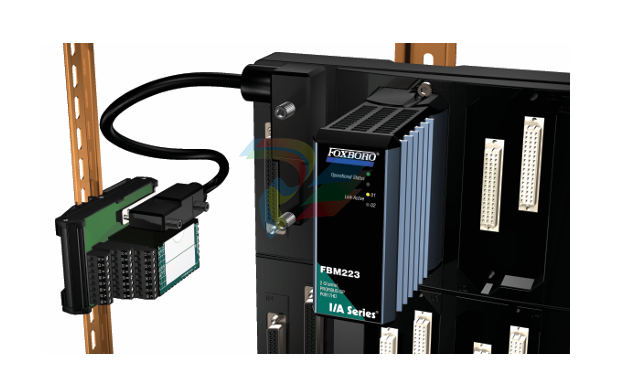
The FBM223 PROFIBUS-DP™ Communication Interface Module provides an interface between
PROFIBUS-DP slave devices and the I/A Series® system.
FEATURES
Key features of the FBM223 module are:
Conforms to PROFIBUS-DP Fieldbus
specifications
Provides full support for all device variables and
diagnostic messages
Integrates PROFIBUS slave device data into an
I/A Series control database
The FBM223 and its associated termination
assembly (TA) are suitable for installation in
Class 1. Division 2 and Zone 2 locations.
OVERVIEW
The PROFIBUS-DP Communication Interface Module
(FBM223) provides an interface between
PROFIBUS-DP slave devices — such as motor
drives, I/O modules, and field I/O devices — and the
I/A Series system.
PROFIBUS is a vendor-independent, open fieldbus
standard for a wide range of applications in process
automation and manufacturing. Vendor
independence and openness are guaranteed by the
PROFIBUS Fieldbus standard EN 50170. which
specifies the functional, electrical, and mechanical
characteristics for a serial transmission bus.
Physical PROFIBUS-DP wiring is in accordance with
Electronic Industrial Association (EIA) standard RS
485.
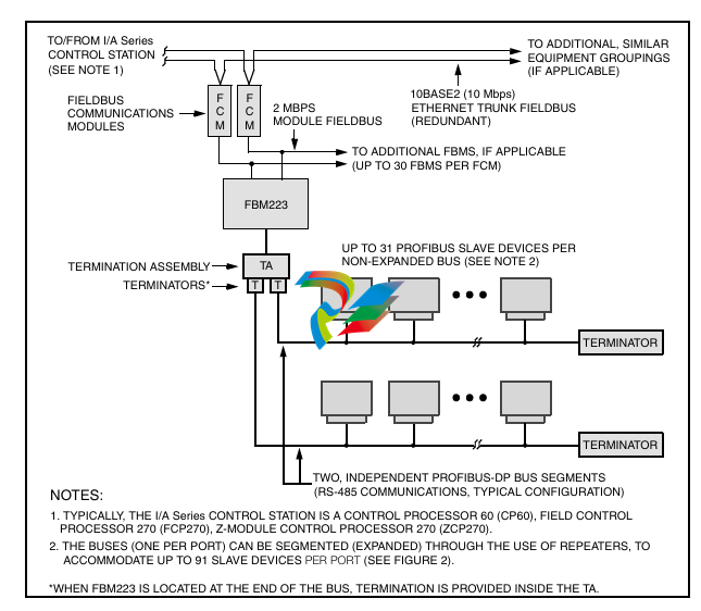
In addition to the general PROFIBUS-DP
configuration shown in Figure 1. several other
configurations are possible, including those using
repeaters and intrinsic safety protective devices.
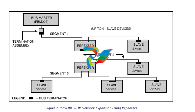
Figure 2 shows how a bus can be expanded into
multiple segments through the use of repeaters, thus
providing support for a greater number of slave
devices.
FBM223 communicates with the PROFIBUS I/O
devices on a master/slave basis. As master, the
FBM223 initializes each data communication
exchange. The slave devices can only acknowledge
received messages, or send messages to the master
when requested to do so.
PROFIBUS-DP TECHNOLOGY
“DP” (in PROFIBUS-DP) represents the
communication profile that is most often used with
PROFIBUS — decentralized periphery. It is optimized
for speed, efficiency, and low connection cost, and is
designed especially for communication between
automation systems (such as the I/A Series control
system) and distributed field devices.
GSD FILES
A GSD file identifies a PROFIBUS-DP device. It
contains information specific to each device and
specifies parameters such as baud rates, timing
information and supported options such as
diagnostics and data length. A GSD file, provided by
the device manufacturer, is available for each device
type.
The data transmission method used with
PROFIBUS-DP is in accordance with EIA standard
RS-485. a proven serial communication technology
used in universal applications in process control and
manufacturing automation. Applications for RS-485
include all areas in which high transmission speed
and simple, inexpensive installation are required. The
physical communication medium consists of twisted
pair shielded copper cable containing a single
conductor pair. Active bus terminators, required at
either end of the bus or bus segment, typically exist
within the bus connectors or within the devices
themselves.
The I/A Series system uses the information in the
GSD file to set up communication to the slave
device. A configurator, available on the operator
station (UNIX® or Windows® based) allows the
importation of such files for establishing supported
options and for validating the values set by the user
NETWORK EXPANSION
Without the use of repeaters (non-expanded bus
configuration) up to 31 slave stations can exist on a
PROFIBUS-DP bus. Depending on the selected data
transfer rate, cabling distances up to 1200 m
(3960 ft) are possible without the use of repeaters
(see Table 1).
The use of repeaters provides for expansion of the
bus, allowing a greater number of slave devices per
FBM223 port, up to 91.
For a given system, with the use of repeaters the
maximum number of slave devices supported on an
FBM223 port is dependent on the amount of I/O that
is configured per device for access by the FBM223.
FBM CAPACITY
For the complete specification of number of devices
supported versus maximum I/O per device, refer to
the PROFIBUS-DP Communication Interface Module
(FBM223) User’s Guide (B0400FE).
From the I/A Series control station to which the
FBM223 is connected (refer to Figure 1), up to 100
connections per FBM223 port can be made to the
I/O data being accessed (read or written) by the
FBM223 over PROFIBUS.
A connection may be to:
An analog input or output value (integer or
floating point)
A string input or output
A single digital input or output value
Multiple (packed) digital input or output values
(packed in groups of up to 32 digital points per
connection).
Thus an I/A Series control station can access up to
100 analog I/O values, or 3200 digital I/O values, or a
combination of digital, analog, and string I/O, via
each of the two ports of the FBM223. The frequency
of access to FBM223 data by a control station may
be as fas
FIELDBUS COMMUNICATION
TERMINATION ASSEMBLY
The Fieldbus Communications Module (FCM) or the
Field Control Processor (FCP) interfaces to the
redundant 2 Mbps module Fieldbus used by the
FBMs. The FBM223 accepts communication from
either path (A or B) of the 2 Mbps Fieldbus — should
one path fail or be switched at the system level, the
module continues communication over the active
path.
MODULAR BASEPLATE MOUNTING
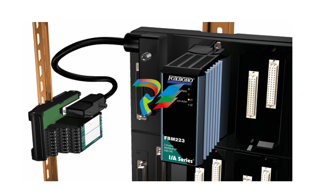
The module mounts on a Modular Baseplate (see
Figure 3), which accommodates up to four or eight
FBMs. The Modular Baseplate is either DIN rail
mounted or rack mounted, and includes signal
connectors for the FBMs, redundant independent dc
power connections, and I/O cable connections.
Features
Key features include:
Combination foot that supports 32 or 35 mm DIN
rail mounting
Distinct family group color
Three-tier termination
Switch-selectable termination resistors.
Overview
Field I/O signals connect to the FBM subsystem via
DIN rail mounted termination assemblies (TAs).
Each FBM223 PROFIBUS-DP Termination Assembly
and its associated termination cable provide feed
through connection between PROFIBUS-DP
compliant field devices and the FBM223
PROFIBUS-DP Communication Input Interface
Module.
The TA is available in Polypropylene (PVC) material.
The DIN rail mounted TAs connect to the Modular
Baseplate by means of a removable termination
cable. The cable is available in a variety of lengths, up
to 30 meters (98 feet), allowing the TA to be mounted
in either the enclosure or in an adjacent enclosure.
Termination cables are available in the following
materials:
Polyurethane
Hypalon® XLP (fire retardant).
Refer to Table 2 on page 11.
FUNCTIONAL SPECIFICATIONS
PROFIBUS-DP Communications
INTERFACE
2 communication channels provide interface to 2
isolated PROFIBUS-DP buses
BUS CHARACTERISTICS
General
Electronic Industrial Association (EIA) RS
485 communications. The physical
communication medium consists of twisted
pair shielded copper cable containing a
single conductor pair.
Data Transfer Rate (Baud Rate)
Selectable, 9.6 to 12.000 kbit/sec (see
Table 1)
FBM223 CHANNEL ISOLATION
Each communication channel is galvanically isolated
and referenced to earth (ground). The module can
withstand, without damage, a potential of 600 V ac
applied for one minute between either channel and
earth.
CAUTION
This does not imply that the channels are
intended for permanent connection to
voltages of these levels. Exceeding the limits
for input voltages, as stated elsewhere in this
specification, violates electrical safety codes
and may expose users to electric shock.
Maximum Allowable Bus Length
The maximum allowable length of a
PROFIBUS-DP bus segment is a function of
the user selected data transfer rate (see
Table 1)
Maximum Cable Length, FBM223 to TA
30 m (90 ft) which is to be included in the
bus segment length
Maximum Number of Devices (Total) on a
Bus
Per EN 50170. for a non-expanded bus
(repeaters not used), one master and up to
31 slaves are supported. For an expanded
bus, the number of slave devices allowed is
a function of the allowable input/output data
processed per slave device (refer to the
PROFIBUS-DP Communication Interface
Module (FBM223) User’s Guide (B0400FE)).
The maximum number supported per port is
91.
Maximum Number of Devices on a Bus
Segment
Per EN 50170. a bus segment (in an
expanded network) supports up to 32 active
devices. An active device can be a master,
slave, or repeater.
FASTEST ALLOWED ECB BLOCK PERIOD
500 msec
Conformance to PROFIBUS-DP Standards
PROFIBUS-DP bus topologies and communications
are in accordance with specifications presented in the
following standards:
PROFIBUS Fieldbus standard EN 50170
EIA standard RS-485.
FBM223 Power Requirements
INPUT VOLTAGE RANGE (REDUNDANT)
24 V dc +5%, -10%
CONSUMPTION
6 W (maximum)
HEAT DISSIPATION
6 W (maximum)
FUNCTIONAL SPECIFICATIONS (CONTINUED)
Regulatory Compliance
ELECTROMAGNETIC COMPATIBILITY (EMC)
European EMC Directive 89/336/EEC
Meets:EN 50081-2 Emission standard
EN 50082-2 Immunity standard
EN 61326 Annex A (Industrial Levels)
CISPR 11. Industrial Scientific and
Medical (ISM) Radio-frequency
Equipment - Electromagnetic Disturbance
Characteristics - Limits and Methods of
Measurement
Meets: Class A Limits
IEC 61000-4-2 ESD Immunity
Contact 4 kV, air 8 kV
IEC 61000-4-3 Radiated Field Immunity
10 V/m at 80 to 1000 MHz
IEC 61000-4-4 Electrical Fast
Transient/Burst Immunity
2 kV on I/O, dc power and communication
lines
IEC 61000-4-5 Surge Immunity
2kV on ac and dc power lines; 1kV on I/O
and communications lines
IEC 61000-4-6 Immunity to Conducted
Disturbances Induced by Radio
frequency Fields
10 V (rms) at 150 kHz to 80 MHz on I/O, dc
power and communication lines
IEC 61000-4-8 Power Frequency
Magnetic Field Immunity
30 A/m at 50 and 60 Hz
IEC 61000-4-11 Voltage Dips, Short
Interruptions and Voltage Variations
ENVIRONMENTAL SPECIFICATIONS(1)
Operating
TEMPERATURE
FBM223-20 to +70°C (-4 to +158°F)
Termination Assembly-20 to +50°C (-4 t
PHYSICAL SPECIFICATIONS
Mounting
MODULE
The FBM223 mounts on a Modular Baseplate.
The Modular Baseplate can be mounted
horizontally or vertically on a DIN rail, or mounted
horizontally in a 19-inch rack using a mounting
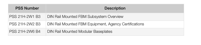
kit. Refer to PSS 21H-2W6 B4 for details.
TERMINATION ASSEMBLY
The TA accommodates multiple DIN styles
including 32 mm (1.26) and 35 mm (1.38 in) rails.
Mass
MODULE
284 g (10 oz) approximate (each module)
TA - COMPRESSION SCREW
363 g (0.8 lb) approximate
Dimensions
MODULE
HEIGHT
102 mm (4 in)
114 mm (4.5 in) including mounting lugs
WIDTH
45 mm (1.75 in)
DEPTH
104 mm (4.11 in)
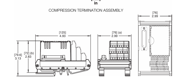
TERMINATION ASSEMBLY
See page 12
Part Numbers
FBM223 MODULE
P0917HD
TA - COMPRESSION SCREW
P0917SY
Indicators (mounted on front of each module)
OPERATIONAL STATUS
Red and green light-emitting diodes (LEDs)
CHANNEL COMMUNICATION ACTIVITY
2 amber LEDs, one per port
Termination Cables
CABLE LENGTHS
Up to 30 m (98 ft).
CABLE MATERIALS
Polyurethane or Hypalon XLP
TERMINATION CABLE TYPE
Type 1 - Refer to Table 2 on page 11
CABLE CONNECTION
Termination Assembly
25-pin male D-subminiature
Modular Baseplate
37-pin male D-subminiature
Termination Assembly Construction Material
MATERIAL
Polypropylene (PVC) Material, compression
screw
FAMILY GROUP COLOR
Green - communication
TERMINAL BLOCKS
Inputs and Outputs - 3 tiers, 8 positions
Field Termination Connections
COMPRESSION-TYPE ACCEPTED WIRING SIZES
Solid/Stranded/AWG
0.2 to 4 mm2/0.2 to 2.5 mm2/24 to 12 AWG
Stranded with Ferrules
0.2 to 2.5 mm2 with or without plastic colla
-
SAMSUNG SMAOC-12 Analog Output Module (12CH)
-
SAMSUNG SMAOC-8 Analog Output Module (8CH)
-
SAMSUNG SMAIC-12 Analog Current Input Module (12CH)
-
SAMSUNG SMRTD-8 RTD Pt100 Temperature Input Module (8CH)
-
SAMSUNG SMAIC-8 Analog Input Module (8CH)
-
SAMSUNG SMDO-8 Digital Output Module (8CH)
-
SAMSUNG SMDI-8 Digital Input Module (8CH)
-
SAMSUNG SMCPU-08 Central Processing Unit Controller
-
Embedded MXM GPU Modules EGX-MXM-A4500 ADLINK
-
Embedded MXM GPU Modules EGX-MXM-AD2000 ADLINK
-
ADLINK Embedded MXM GPU Modules EGX-MXM-AD3500
-
ADLINK Embedded MXM GPU Modules EGX-MXM-AD5000
-
Embedded MXM GPU Modules EGX-MXM-AD ADLINK
-
Embedded MXM GPU Modules MXM-AXe ADLINK
-
ADLINK Embedded MXM GPU Modules EGX-MXM-BW500
-
Embedded MXM GPU Modules EGX-MXM-BW2000 ADLINK
-
ADLINK Embedded MXM GPU Modules EGX-MXM-BW4000
-
Embedded MXM GPU Modules EGX-MXM-BW5000 ADLINK
-
SAMSUNG SSAS-PRO SPTB-AI dedicated analog input terminal board
-
SAMSUNG SSAS-PRO SPTB-DO dedicated digital output terminal board
-
SAMSUNG SSAS-PRO SPTB-DI dedicated terminal board
-
SAMSUNG SSAS-PRO SPBK-X32-12 Heavy-duty 8-slot system chassis backplane
-
SAMSUNG SSAS-PRO SPBK-X32-08 Heavy-duty 8-slot system chassis backplane
-
SAMSUNG SSAS-PRO SPSU-X32 heavy-duty rack-mounted
-
SAMSUNG SSAS-PRO SPIRU-16 versatile universal mixed I/O module
-
SAMSUNG SSAS-PRO SPRI-16 RTD Temperature Input Module
-
SAMSUNG SSAS-PRO SPAO-8 Analog Output Module
-
SAMSUNG SSAS-PRO SPAI-16 Analog Input Module
-
SAMSUNG SSAS-PRO SPRDO-16 Relay digital output module
-
SAMSUNG SSAS-PRO SPDO-16 (Transistor Digital Output Module)
-
SAMSUNG SSAS-PRO SPDI-24 high-density digital input module
-
SAMSUNG SPDI-16 (Digital Input Module)
-
ADLINK 3U Enclosures & Systems AD-3100
-
Power Supplies cPS-H300S/AC ADLINK
-
CPCI Serial Peripheral cPCI-A3H10 ADLINK
-
ADLINK CPCI Serial Peripheral cPCI-A3XMC
-
CPCI Serial Peripheral cPCI-A3H20 ADLINK
-
CPCI Serial Peripheral cPCI-A3MXM ADLINK
-
ADLINK CPCI Serial Peripheral cPCI-A3COM
-
ADLINK CPCI Serial Peripheral cPCI-A3USB
-
ADLINK CPCI Serial Peripheral cPCI-A3ETH
-
CPCI Serial Peripheral cPCI-A3CAN ADLINK
-
3U CompactPCI Serial Blades cPCI-A3525 Series
-
3U CompactPCI Serial Blades cPCI-A3535 Series ADLINK
-
CompactPCI Backplanes cBP-6402 ADLINK
-
ADLINK CompactPCI Backplanes cBP-6402R
-
ADLINK CompactPCI Backplanes cBP-6105R
-
CompactPCI Backplanes cBP-6405R ADLINK
-
CompactPCI Backplanes cBP-6108F ADLINK
-
CompactPCI Backplanes cBP-6108R ADLINK
-
CompactPCI Backplanes cBP-6014R ADLINK
-
ADLINK 6U Enclosures & Systems cPCIS-6130R
-
ADLINK 6U Enclosures & Systems cPCIS-6230R/ 6240R Series
-
ADLINK 6U Enclosures & Systems cPCIS-6235R
-
ADLINK 6U Enclosures & Systems cPCIS-6400X Series
-
ADLINK 6U Enclosures & Systems cPCIS-6400U Series
-
ADLINK 6U Enclosures & Systems cPCIS-6418U
-
ADLINK 6U Enclosures & Systems cPCIS-3300BLS
-
ADLINK 6U Enclosures & Systems cPCIS-3320/AC
-
ADLINK Power Supplies cPS-H640/AC
-
ADLINK Power Supplies cPS-H640/48
-
ADLINK 6U Rear Transition Modules cPCI-R6100 Series
-
ADLINK 6U Rear Transition Modules cPCI-R6002 Series
-
ADLINK 6U Rear Transition Modules cPCI-R6600 Series
-
ADLINK 6U CompactPCI 2.0 Blades cPCI-6660
-
ADLINK 6U CompactPCI 2.0 Blades cPCI-6636(KL) Series
-
ADLINK 6U CompactPCI 2.0 Blades cPCI-6640 Series
-
ADLINK 6U CompactPCI 2.0 Blades cPCI-6540 Series
-
ADLINK CompactPCI Backplanes cBP-3064
-
ADLINK CompactPCI Backplanes cBP-3213PR
-
ADLINK 3U Enclosures & Systems cPCIS-2500 Series
-
ADLINK 3U Enclosures & Systems cPCIS-2630 Series
-
ADLINK 3U Enclosures & Systems cPCIS-2632 Series
-
ADLINK 3U Enclosures & Systems cPCIS-2642 Series
-
ADLINK U Enclosures & Systems cPCIS-2633 Series
-
ADLINK U Enclosures & Systems cPCIS-ET1100 Series
-
ADLINK Power Supplies cPS-H325/AC
-
ADLINK Power Supplies cPS-H325/48
-
ADLINK Power Supplies cPS-H325/110
-
ADLINK Power Supplies cPS-H325/24
-
ADLINK PCI-7841/cPCI-7841 Dual-port Isolated CAN Interface Cards
-
ADLINK Peripherals & Accessories cPCI-3548
-
ADLINK Peripherals & Accessories cPCI-8301
-
ADLINK Peripherals & Accessories cPCI-3W10
-
ADLINK Analog Output cPCI-6208/6216 Series
-
ADLINK Multi-Function DAQ cPCI-9116
-
ADLINK 3U CompactPCI Blades CT-3620
-
ADLINK 3U CompactPCI Blades cPCI-3620
-
ADLINK 3U CompactPCI Blades cPCI-3620
-
ADLINK 3U CompactPCI Blades cPCI-3630
-
ADLINK 3U CompactPCI Blades cPCI-3640 Series
-
3U CompactPCI Blades cPCI-3520 Series
-
ADLINK IMB-M42H ATX Motherboards
-
Adlink PCIe-GIE74 /PCIe-GIE74V Frame Grabbers / Video Capture Cards
-
ADLINK USB-1605 Removable screw terminal blocks or high-density D-Sub
-
Adlink ETX-NR667-L7400/LXE ETX Module
-
ADLINK NuPRO-842LV/P industrial control motherboard
-
ADLINK cPCI-8994 Serial Communication
-
ADLINK / PCI-7432 Digital I/O
-
ADLINK IEC-915GV Compact industrial-grade fanless embedded system
-
ADLINK ADLINK, PLX / PCI-7296 Digital I/O
-
ADLINK HPCI-14S12U 0040 Backplane Selection Guide
-
ADLINK MXE-5500 /MXE-5501/M16G (G) Fanless Embedded Computer
-
Adlink Multi-Function DAQ PCI-9112
-
ADLINK NuPRO-852LV Control Board
-
ADLINK CompactPCI cPCI-7432R Digital I/O Module
-
ADLINK NUPRO-E320LV PICMG Single Board Computers
-
ADLINK PICMG Single Board Computers NuPRO-E72
-
ADLINK PICMG Single Board Computers NuPRO-865
-
Vibro-Meter Rack VM600SYSMK2-ABE04x 6U 19-inch rack Mk2 system
-
Vibro-Meter Relay expansion RLC16 Mk2 SIL2 (single card) 600-044L
-
Vibro-Meter Relay expansion RLC16 Mk2 SIL2 600-04
-
Vibro-Meter Relay expansion RLC16 Mk2 600-045L
-
Vibro-Meter Relay expansion RLC16 Mk2 600-045
-
Vibro-Meter I/O interface card IOCN Mk2 600-051
-
Vibro-Meter CPU controller CPUM Mk2 600-050
-
Vibro-Meter I/O interface card IOC10 Mk2 (rear card) 600-046
-
Vibro-Meter Temperature / Analog Acquisition AMC10 Mk2 600-042
-
Vibro-Meter I/O interface card IOC4 Mk2 600-043
-
Vibro-Meter Protective measuring card MPC4 Mk2 SIL2 601-041-A10
-
Vibro-Meter Protective measuring card MPC4 Mk2 601-041-A0
-
Vibro-Meter PSU-VM600 VM600 Rack Power Module
-
Vibro-Meter ABE056 - 1U ultra-thin single-rack
-
Vibro-Meter ABE046 - 6U 19-inch rack
-
Vibro-Meter ABE045 - 6U 19-inch rack
-
Vibro-Meter ABE044 - 6U 19-inch rack (with expansion slots)
-
Vibro-Meter ABE042 6U 19-inch rack (4 slots)
-
Vibro-Meter I/O interface card XIO16T

Add: High-tech Software Park, Xiamen City, Fujian Province
Mobile: +86-17750019513(WhatsApp)
Email: yy4291644@gmail.com
Website: https://www.abb-sis.com
.jpg)
.jpg)
.jpg)
.jpg)
.jpg)
.jpg)

-
SAMSUNG SMAOC-12 Analog Output Module (12CH)
-
SAMSUNG SMAOC-8 Analog Output Module (8CH)
-
SAMSUNG SMAIC-12 Analog Current Input Module (12CH)
-
SAMSUNG SMRTD-8 RTD Pt100 Temperature Input Module (8CH)
-
SAMSUNG SMAIC-8 Analog Input Module (8CH)
