

Kongsberg d0000930 presafe-atex-report signed
General product information:
Abbreviations used are: DUT: Devices Under Test (built-in modules). KM: Kongsberg Maritime AS
Built-in modules included in this investigation are:
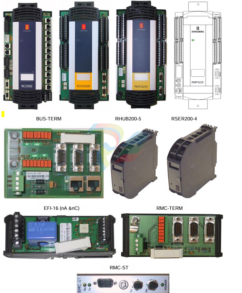
Modules Art. No. Description Specs
RAIV400 600370 Remote Analogue Input Voltage 24Vdc, max 0.9A power consumption. Heat
dissipation10W
RDIO420S 316564 Remote Digital Input Output 24Vdc, max 0.9A power consumption. Heat
dissipation10W
RMP420 306712 Remote Multipurpose I/O 24Vdc, 10W, Loop current max 1A per channel
RMP420S 319824 RMP420S (S version) 24Vdc, 10W, Loop current max 1A per channel
RMP422 388820 Remote Multipurpose I/O 24Vdc, 10W, Loop current max 1A per channel
RMP422S 363350 RMP422S (S version) 24Vdc, 10W, Loop current max 1A per channel
RCU502 330924 Remote Control Unit 24Vdc, 20W power consumption, 20W heat
dissipation
RSER200-4 603444 Serial Line Interface 24Vdc, 160mA
RHUB200-5 603442 RBUS Hub 24Vdc, 100mA
BUS-TERM 310955 BUS-Termination 24Vdc
RMC-TERM 346007 Remote Media Converter Termination 24Vdc
RMC-ST 321520 Remote Media Converter-ST 24Vdc, 80mA
EFI-16 321492 Earth Fault Indicator 24Vdc, max 100mA
Refer to Hardware Module Description (HMD) for comprehensive details of technical specifications
Intended use.
The built-in modules are intended for different application as parts of communication system/station. The cabinets
required for these built-in modules must have minimum IP54 rating. ‘X’-marking associated to special condition of
use is used. However safety concern was taken into account in considerations for relevant tests (e.g. thermal
endurance test).
Since external cabinet and the number of used modules at the end application are unknown, safety concern relied
on special condition of use. See ‘Condition of Use’. The internal temperatures are in any cases monitored by the
control system, e.g. internal air temperature.
Investigation of modules RMP420S & RMP422S (S-versions) is considered to be representative for modules
RMP420 & RMP422 since electronics is the same, only software may be different. The later designed module
RMP422S has multipurpose application which may/can cover the usage of several other listed modules as well.
Reset-switch and other addressable switch on a few modules may also be used only during testing/service/repair
or initializing start-up procedure of DUT where the service personnel must follow the normal safety procedures
before any service/repair work. See Special condition of use. Those switches are not used in normal operation
mode. Warning and safety precaution are provided for these switches and their application. See Copy of marking
plate.
Design.
All modules have internal transient protection except for module. RSER200-4 module is however interconnected
between other modules with internal transient protection. All modules have power dissipation approximately to or
less than 20W, therefore these built-in modules are considered as non-sparking low power equipment complying
with clause 13 of IEC60079-15: 2010. Requirements of creepage & air clearance distances are exempted. The
operating input voltage for all modules is 24Vdc, all secondary analogue and digital voltages are derived from
24Vdc input for functional purposes. Assessments are based therefore on 24Vdc as the only operating voltage.
0V reference of 24Vdc input is connected to module’s metal frame. DUT may be earthed in the end installation
and may be evaluated in the end use. Power supply with galvanic separation must be used in the end application.
Connection facilities and suitable terminals are provided. The cable lug connection may be used only during
testing or initializing start-up procedure of DUT. Cable lug is not used otherwise in normal operation mode. All
wiring is to be internal in the end installation.
General product information:
The module EFI-16 Earth Fault Indicator is used to monitor the input and output current and which indicates an
earth fault. Relay K1 on EFI-16 module is investigated for ‘nC’ requirements of IEC60079-15: 2010. Module EFI
16 is therefore evaluated for nA & nC type of protection.
Opto-couplers are used as functional separation for I/O signal of communication system. Opto-couplers have no
safety function and are treated as any other ICs due to the fact that investigation is based on requirements of
non-sparking low power equipment.
Test configuration / considerations
Built-in modules have different rated input voltage range. The output current on I/O channels are consequently
controlled & distributed so that the thermal & power aspects do not exceed the defined limits. All channels are
short circuit protected. For high current outputs the cut-off point is by default limited to 1.08 Amp for each
channel, regardless of the supplied voltage (18 – 32VDC). Output is shutdown at input voltage less than the max
rated voltage due to this reason. Thermal condition and current are monitored and are controlled by the ma
Measurement Section, including Additional Narrative Remarks (as deemed applicable)
Clause 5.3 Maximum surface temperatures
Clause 26.5 Thermal tests. Temperatures measurements documented in Appendix B.1 of the associated
IEC60079-15 Test report.
Clause 7.2 Thermal endurance:
Clause 26.8 & 26.9 Thermal endurance to heat & cold. Modified tests according to Table 1 of IEC60079-15:
2010. Thermal endurance tests documented in Appendix B.3 of the associated IEC60079-15 Test report.
Non-metallic assembly part of investigated modules (Mounting frame for PCB) is considered to be part of
enclosure in the end use. The used non-metallic material is ZYTEL Nylon resin type FR72G25V0. V-0. RTI=
120°C (Imp), CTI code 2. UR E41938.
Table 26.8 Thermal endurance to heat P 2)
Part tested Test condition Remark
DUT 1) Climatic conditioning in 672h at 80°C & 90% RH. 3) No visible deterioration of material.
Supplementary information:
1) Four I/O modules and three separate K1 relay of module EFI-16 tested, RCU502 & RMP420 &
RAIV400 & EFI16 & K1 relays. Results are representative for all modules which are included in the
investigation.
2) Thermal endurance to heat test is modified according to requirements of cl. 22.3.1 of IEC60079-15:
2010
3) Built-in I/O modules tested. No cabinets included in the investigation. Maximum service temperature is
determined in associated IEC60079-15: 2010 test report. However taking into account the end
application where mounting condition and environmental influences might have impact on the end use,
maximum service temperature is based on the stated ‘Specific condition of use’.
Table 26.9 Thermal endurance to cold P
Part tested Test condition Remark
DUT 1) Climatic conditioning in 24h at -30°C. No visible deterioration of material.
Supplementary information:
1) Four I/O modules tested, RCU502 & RMP420 & RAIV400 & EFI16. Results are representative for all
modules
-
CTI 2572-B Fast Ethernet TCP/IP Adapter
-
CTI 2576 DeviceNet™ Scanner Module (MATURE)
-
CTI 2500P-ECC1 Ethernet Communications Coprocessor
-
CTI 2500P-JACP Janus Application Coprocessor
-
CTI 2500P-ACP1 Application Coprocessor (MATURE - replaced by 2500P-JACP)
-
CTI 2500P-J450 Janus PAC with 2MB Project Memory
-
CTI 2500-C400 CPU with 3072K User Memory
-
CTI 2500-C300 CPU with 512K User Memory
-
CTI 2500-C200 CPU with 256K User Memory
-
CTI 2500-C100 CPU with 128K User Memory
-
CTI 2500P-J750 Janus PAC with 3MB Project Memory
-
Shinkawa WHF3006M Displacement Converter
-
Shinkawa JBP-220 (P-24-94A / P-24-94B) Circuit Board Module
-
SHINKAWA WKN-142K5 2-WIRE VIBRATION TRANSDUCER
-
Shinkawa FRP-321 (P-26-54A / P-26-54B) Circuit Board Module
-
Shinkawa IOP-160 (P-25-72A / P-25-72B) Circuit Board Module
-
Shinkawa PK-147B-1 / PK-147A-1 Circuit Board Module
-
Shinkawa CPP-91A Circuit Board Module
-
Shinkawa FRP-177 PCB Module
-
Shinkawa CPP-127 (P-26-74A / P-26-74B) Circuit Board Module
-
Shinkawa FRP-227 (P-24-86A / P-24-86B) Circuit Board Module
-
Shinkawa MDP-104 (P-25-83A / P-25-83B) Circuit Board Controller
-
Shinkawa VK-143P2 High-precision eddy current sensor driver/signal conditioner
-
Shinkawa FRP-226 (P-24-86A / P-24-86B) Circuit Board Module
-
Shinkawa CPP-107A P-22-99A P-22-99B Circuit Board Module
-
SHINKAWA VW-202AL-8 Axial Displacement Sensor
-
Shinkawa VL-202A08L-1A42 Vibration Sensor Transducer Probe
-
Shinkawa FRP-209A & FRP-206 Wire Bonder Circuit Board Module
-
Shinkawa MGP-72 MGP72 P-26-50A P-26-50B Circuit Board Module
-
Shinkawa FRP-249 P-25-1A P-25-1B Circuit Board Module
-
Shinkawa FRP-320 P-26-54A P-26-54B Circuit Board Module
-
Shinkawa FRP-282 P-24-35A P-24-35B Circuit Board Module
-
Shinkawa FRP-338 P-26-54A P-26-54B Circuit Board Module
-
GE IS200AEPBH1B Pitch-Charger Control PCB Board
-
GE IS200EDEXG1ADA EX2100 SCR Trigger Control Board
-
GE 151X1207CK01SA01 IS200EDEXG1A EX2100 SCR
-
GE 151X1233DD02SA02 IS200AEPBH1B - Variant for pitch control charger assembly
-
GE 151X1233DB01SA01 IS200AEPBH1B - 10kW Wind Power Converter
-
GE 151X1233DB01SA01 IS200AEPBH1B - 10kW Wind Power Converter
-
GE 151X1233DB01SA01R | IS200AEPBH1B 10KW Converter
-
GE 151X1233DD01SA02 Pitch Battery Charger (109W6931P001)
-
GE 151X1233DD01SA02 Pitch Battery Charger Assy IS200AEPBH1B
-
GE 151X1233DB02SA02 Rev A IS200AEPBH1B Wind Turbine Converter
-
GE 151X1207CK02SA02 SCR 4400 V 1850 A IS200EDEXG1ADA General Electric EX2100
-
Triconex 3723X 32-Channel TMR Analog Input Module with HART
-
SHINKAWA VM-21G SIGNAL CONDITIONER SOCKET
-
SHINKAWA VM-21R REVOLUTION SIGNAL CONDITIONER
-
SHINKAWA VM-21T DISPLACEMENT INPUT THRUST SIGNAL CONDITIONER
-
SHINKAWA VM-21D 6-WIRE LVDT SIGNAL CONDITIONER
-
SHINKAWA VM-21P 3-WIRE LVDT SIGNAL CONDITIONER
-
SHINKAWA VM-21A VIBRATION SIGNAL CONDITIONER
-
SHINKAWA VM-21K DISPLACEMENT INPUT VIBRATION SIGNAL CONDITIONER
-
SHINKAWA VM-25S01 CONDITION MONITORING SYSTEM
-
SHINKAWA VM-25 CONDITION MONITORING SYSTEM
-
SHINKAWA VM-772B DEVICE CONFIG
-
SHINKAWA VM-771B MCL VIEW
-
SHINKAWA VM-76B INSTRUMENT RACK
-
SHINKAWA VM-75B POWER SUPPLY MODULE
-
SHINKAWA VM-742B NETWORK COMMUNICATION MODULE
-
SHINKAWA VM-741B LOCAL COMMUNICATION & PHASE MARKER MODULE
-
SHINKAWA VM-722B 9-CHANNEL RELAY MODULE
-
SHINKAWA VM-707B AERODERIVATIVE GAS TURBINE MONITOR MODULE
-
SHINKAWA VM-706B ROD DROP MONITOR MODULE
-
SHINKAWA VM-705B 18-CHANNEL TEMPERATURE MONITOR MODULE
-
SHINKAWA VM-704B TEMPERATURE MONITOR MODULE
-
SHINKAWA VM-703B TACHOMETER & ECCENTRICITY MONITOR MODULE
-
SHINKAWA VM-702B ABSOLUTE VIBRATION MONITOR MODULE
-
SHINKAWA VM-701B VIBRATION / DISPLACEMENT MONITOR MODULE
-
SHINKAWA MODEL VM-5X INTERFACE UNIT
-
SHINKAWA MODEL VM-5W2 DUAL POWER SUPPLY INSTRUMENT RACK
-
SHINKAWA MODEL VM-5H4 INSTRUMENT RACK (for VM-5Z5.6.7)
-
SHINKAWA MODEL VM-5G SINGLE UNIT INSTRUMENT RACK
-
SHINKAWA MODEL VM-5Z5,6,7 POWER SUPPLY UNIT
-
SHINKAWA MODEL VM-5Y1,2,3 RELAY MODULE UNIT
-
SHINKAWA MODEL VM-5P3 PHASE MARKER UNIT
-
SHINKAWA MODEL VM-53 DUAL COMMUNICATION UNIT
-
SHINKAWA MODEL VM-52 BOTTOM HOLD MONITOR
-
SHINKAWA MODEL VM-51 ROD DROP MONITOR
-
SHINKAWA MODEL VM-5R TACHOMETER
-
SHINKAWA MODEL VM-5S DUAL TACHOMETER
-
SHINKAWA MODEL VM-5A DUAL VALVE
-
SHINKAWA MODEL VM-5E DUAL CASE
-
SHINKAWA MODEL VM-5L COMPLEMENTARY INPUT
-
SHINKAWA MODEL VM-5N RAMP DIFFERENTIAL
-
SHINKAWA MODEL VM-5D DUAL DIFFERENTIAL
-
SHINKAWA MODEL VM-5T DUAL THRUST MONITOR
-
SHINKAWA MODEL VM-5C ECCENTRICITY MONITOR
-
SHINKAWA MODEL VM-5C ECCENTRICITY MONITOR
-
SHINKAWA MODEL VM-5M DUAL PATH MONITOR
-
SHINKAWA MODEL VM-5B DUAL ACCELERATION MONITOR
-
SHINKAWA MODEL VM-5B DUAL ACCELERATION MONITOR
-
SHINKAWA MODEL VM-5U DUAL SEISMIC MONITOR
-
SHINKAWA MODEL VM-55 VIBRATION MONITOR
-
SHINKAWA VM-742B1-5 VIBRATION MONITORING SYSTEM CARD
-
Shinkawa PSP-17B P-24-64A P-24-64B Circuit Board Module
-
SHINKAWA MGP-67 PCB
-
Shinkawa JBP-278 P-22-48A-1 P-22-48B-1 Circuit Board Module
-
Shinkawa VM-721B 18-CHANNEL RELAY MODULE
-
Shinkawa FRP-337 P-26-54A P-26-54B Circuit Board Module
-
Shinkawa WKN-142K2-2 Vibration Transmitter
-
SHINKAWA VL-202A08L-1012 Rotor Position Monitor Probe Sensor
-
Shinkawa CPP-128 P-26-74A P-26-74B Circuit Board Module
-
Honeywell 51402755-100 PROCESSOR CARD
-
Honeywell 51107595-100 Power
-
HONEYWELL 51304544-100 Control Board
-
HONEYWELL 51109919-100 BOARD
-
HHoneywell 51204160-175 Digital Input Module
-
Honeywell 51304754-150 High Level Analog Input Module
-
HONEYWELL 51304690-100 DIGITAL INPUT CARD
-
Honeywell 51401635-150 COMM CONTROL
-
HONEYWELL 51204174-175 MC-TAOY 52 ANALOG OUTPUT BOARD
-
HONEYWELL 51400596-100
-
HONEYWELL 51401291-100 board card
-
HONEYWELL 51401642-150 I/O LINK MODULE
-
Honeywell LCN‑E Hub Power Supply 38500148‑300
-
Honeywell LCN‑E Hub redundant 38500143‑202 Twisted‑pair LCN
-
Honeywell LCN‑E Hub non‑redundant,38500143‑102
-
Honeywell Enhanced Micro‑TDC‑3000 System Unit MX‑DTAC01K2
-
Honeywell Enhanced Micro‑TDC‑3000 System Unit MX‑DTAB01K2
-
Honeywell Enhanced Micro‑TDC‑3000 System Unit MT11‑520
-
Honeywell STI‑CE Smart Transmitter Interface 51304516‑150
-
Honeywell STI Smart Transmitter Interface 51304516‑100 MC‑PSTX02
-
Honeywell ulse Counter IOP 51304386‑100 MU‑PPIX02
-
Honeywell DO Digital Output IOP‑CE 51304487‑150 CE version
-
Honeywell DO Digital Output IOP 51304487‑100 MC‑PDOX02
-
Honeywell TDC‑3000 SOE DI IOP,51402625-175 MC‑PDIS12
-
Honeywell TDC‑3000 DI Digital Input IOP‑CE 51304485‑150
-
Honeywell TDC‑3000 DI Digital Input IOP 51304485‑100 MC‑PDIX02

Add: High-tech Software Park, Xiamen City, Fujian Province
Mobile: +86-17750019513(WhatsApp)
Email: yy4291644@gmail.com
Website: https://www.abb-sis.com
.jpg)
.jpg)
.jpg)
.jpg)
.jpg)
.jpg)

-
CTI 2572-B Fast Ethernet TCP/IP Adapter
-
CTI 2576 DeviceNet™ Scanner Module (MATURE)
-
CTI 2500P-ECC1 Ethernet Communications Coprocessor
-
CTI 2500P-JACP Janus Application Coprocessor
-
CTI 2500P-ACP1 Application Coprocessor (MATURE - replaced by 2500P-JACP)
