

SEG HighTECH Line MRN3 PROTECTION TECHNOLOGY MADE SIMPLE MAINS
SEG HighTECH Line MRN3 PROTECTION TECHNOLOGY MADE SIMPLE MAINS
Introduction and application
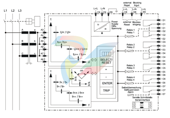
The MRN3 is a universal mains decoupling device and covers the protection requirements from VDEW and most other utilities for the mains parallel operation of power stations. Over/ and under voltage protection, over/ and under frequency protection, extremely fast decoupling of generator in case of mains failure (MRN3-1) or rate of change of frequency df/dt (MRN3-2) Because of combination of three protection functions in one device the MRN3 is a very compact mains decoupling device. Compared to the standard used single devices it has a very good price/performance ratio. For applications where the single protection functions are required SEG Electronics GmbH can offer the single MR-relays as follows: MRU3-1 four step independent over-/ and under voltage protection (also used for generator earth fault protection). MRU3-2 two step independent over-/ and under-voltage protection with evaluation of the symmetrical voltage components. MRF3 four step independent over/ and under- frequency protection and two step frequency gradient supervision df/dt. MRG2 generator mains monitor / vector surge detection.

Features and characteristics
Microprocessor technology with watchdog, effective analog low pass filter for suppressing harmonics when measuring frequency and vector surge, digital filtering of the measured values by using discrete Fourier analysis to suppress higher harmonics and d.c. components induced by faults or system operations, integrated functions for voltage, frequency and vector surge in one device as well as single voltage, frequency and vector surge devices, two parameter sets, voltage supervision each with two step under-/and overvoltage detection, frequency supervision with three step under-/or over frequency (user setting), completely independent time settings for voltage and frequency supervision, adjustable voltage threshold value for blocking frequency and vector surge measuring, display of all measuring values and setting parameters for normal operation as well as tripping via a alphanumerical display and LEDs, display of measuring values as primary quantities Storage of trip values and switching-off time (tCBFP) of 5 fault occurrences (fail-safe of voltage), recording of up to eight fault occurrences with time stamp for blocking the individual functions by the external blocking input, parameters can be set according to requirement, user configurable vector surge measurement 1-of-3 or 3-of-3, reliable vector surge measuring by exact calculation algorithm, suppression of indication after an activation (LED flash), free assignment for output relays, display of date and time, in compliance with VDE 0435, part 303 and IEC 255, serial data exchange via RS485 interface possible; alternatively with RS485 Pro-Open Data Protocol or Modbus Protocol.
3.1.1 Analog input circuits The analog input voltages are galvanically decoupled by the input transformers of the device, then filtered and finally fed to the analog digital converter. The measuring circuits can be applied in star or delta connection (refer to chapter 4.3.1). 3.1.2 Blocking input The blocking function can be set according to requirement. By applying the auxiliary voltage to D8/E8, the previously set relay functions are blocked (refer to 4.8 and 5.7.1). 3.1.3 Reset input Please refer to chapter 5.9.1.
3.1.4 Output relays The MRN3 is equipped with 5 output relays. Apart from the relay for self-supervision, all protective functions can be optionally assigned: Relay
1: C1, D1, E1 and C2, D2, E2 Relay
2: C3, D3, E3 and C4, D4, E4 Relay
3: C5, D5, E5 Relay
4: C6, D6, E6 Relay
5: Signal self-supervision (internal failure of the unit) C7, D7, E7 All trip and alarm relays are working current relays, the relay for self supervision is an idle current relay.
3.1.5 Fault recorder The MRN3 has a fault value recorder which records the measured analog values as instantaneous values. The instantaneous values UL1; UL2; UL3 for star connection or U12; U23; U21 for delta connection are scanned at a raster of 1.25 ms (at 50 Hz) and 1.041 ms (at 60 Hz) and saved in a cyclic buffer. It is possible to store 1 - 8 fault occurrences with a total recording time of 16 s (with 50 Hz) and 13.33 s (with 60 Hz) per channel.
Storage division Independent of the recording time, the entire storage capacity can be divided into several cases of disturbance with a shorter recording time each. In addition, the deletion behavior of the fault recorder can be influenced. No writing over If 2, 4 or 8 recordings are chosen, the complete memory is divided into the relevant number of partial segments. If this max. number of fault event has been exceeded, the fault recorder block any further recordings in order to prevent that the stored data are written over. After the data have been read and deleted, the recorder to ready again for further action. Writing over If 1, 3 or 7 recordings are chosen, the relevant number of partial segments is reserved in the complete memory. If the memory is full, a new recording will always write over the oldest one.
-
Kollmorgen AKM54G-ANC2DB00 servo motor
-
Kollmorgen S200 Series S20350-VTS SERVO DRIVE
-
KOLLMORGEN AKD-P00606-NBCC-I000 SERVO DRIVE
-
Kollmorgen MV65WKS-CE310/22PB Servo Drive Control Module
-
Kollmorgen S20360-VTS-021 Servo Drive
-
KOLLMORGEN CR06550 High-precision digital servo amplifier
-
KOLLMORGEN DBL5N01050-03S-VV0-S40 Phase AC Synchronous Brushless Servo Motor
-
KOLLMORGEN S70301-NANANA-024 SERVO DRIVE
-
Kollmorgen S20360-VTS S200 Series Servo Drive
-
Kollmorgen RBE-03011-A00 Brushless Frameless Servo Motor
-
KOLLMORGEN AKD-T00306-NBAN-0000 INPUT SERVO DRIVE
-
KOLLMORGEN S700 Servo Controller S70302-NANANA
-
Kollmorgen AKD-P00607-NBEC-0000 400/480VAC 4.40KVA Servo Drive.
-
KOLLMORGEN S70102-NANANA SERVO DRIVE
-
KOLLMORGEN AKM21E-ANSNEH02 PM Servo Motor & PRD-AMPE25EB-00 Servo Drive Array
-
KollMorgen SC1R06260 Servo Drive 1.4/2.2 KVA 115230 Vac
-
Kollmorgen AKD-P00306-NBAN-0000 Servo Drive
-
Kollmorgen TTB2-2042-3052-A DC Motor Industrial Drive 5.5A 185 oz/inIntegrated safety
-
KOLLMORGEN SERVOSTAR 610-AS SERVO AMPLIFIER_SERVOSTAR610AS_S61001
-
KOLLMORGEN Seidel 60WKS-CE240/26PB 26A Servo Drive Module Control 60WKS-M240/26
-
KOLLMORGEN PRD-0016400P-10 & PRD-0016600D-30 Axis Control System Modules
-
KOLLMORGEN Seidel DBL5N01700-03S-000-S40 Servo Motor
-
HIRSCHMANN RS30-0802O6O6SDAP RAIL SWITCH
-
Hirschmann RS20-1600M2T1SDAEHH03.1.02 Rail Switch
-
Hirschmann RSPM20-4T14T1EV9HHS999.9.99 Managed Ethernet Switch
-
Hirschmann BELDEN RS40-0009CCCCSDAPHH09.0.14 / RS400009CCCCSDAPHH09014
-
Hirschmann RS40 Rail Switch RS40-0009CCCCSDAE
-
Hirschmann BELDEN RS30-0802T1T1SDAP / RS300802T1T1SDAP Fully Managed Layer 2 Compact Rail Switch
-
Hirschmann BELDEN RS20-0800M2M2SDAUHH / RS200800M2M2SDAUHH
-
Hirschmann EAGLE30-04022O6TT999SCCY9HSE3F Industrial Firewall Router Switch
-
Hirschmann RS20-1600T1T1SDAEHH09.0.14 RS20 Rail Mount Ethernet Switch
-
Hirschmann EAGLE 0200T1T1TDDY90000HHE05.3.03 Industrial Security Router
-
Hirschmann - BELDEN MIPP-AD-1L9P
-
HIRSCHMANN RSPM20-4Z64Z6TV9HHS9 942 106-999 RAIL SAFETY SWITCH
-
HIRSCHMANN FIBEROPTIC MODULE FIP P/N: OZDFIPG3 T
-
HIRSCHMANN RS20-1600M2M2SDAUHH Ethernet rack-mounted switch
-
BELDEN RS20-0400T1T1SDAEHH04.0.01 / RS200400T1T1SDAEHH04001
-
HIRSCHMANN MM2-4FXM3 MICE Media Module
-
Hirschmann RS20-2400T1T1SDAP / RS20-2400T1T1SDAPHH05.0.02
-
GE MLJ1005B010H00C MLJ Digital Synchromism Check
-
ALSTOM MICROTECH DX21-M2 Digital Excitation Controller
-
HIRSCHMANN BRS20-1200ZZZZ-STCY99HHSES
-
HIRSCHMANN MM3-4FXM2 MICE Media Module
-
Hirschmann RSB20-0800T1T1SAABHH 8Port ENet Rail Switch RSB20
-
Hirschmann MACH102-8TP Ethernet Switch
-
SAACKE DDZ-M marine steam pressure atomizer
-
SAACKE SKV-A marine rotary cup atomizer
-
SAACKE Seavis HMI05e
-
Kollmorgen MMC-SD-2.0-230 Servo Drive 100-240VAC 2KW 10A Output 3PH 100-240VAC
-
Kollmorgen Servo drive CR10550
-
Kollmorgen AKD-P01207-NACN-0054 Servo Driver
-
Kollmorgen S406M-CA-036 Servostar
-
Kollmorgen AKD-B02407-NAAN-0000 Digital Servo Drive
-
Kollmorgen SERVOSTAR S406AM-CA Digital Servo Drive
-
KOLLMORGEN SERVOSTAR 603-AS SERVO AMPLIFIER_SERVOSTAR603AS_S60301
-
Kollmorgen S700 Servo Controller (S70602-NANANA-NA)
-
Kollmorgen MPK411 controller
-
KOLLMORGEN MMC-SD-1.3-460-D Smart Drive
-
KOLLMORGEN AKM21C-CKB2AA-00 / AKM21CCKB2AA00 Servomotor
-
BECKHOFF AX5106-0000-0200 | Digital Compact Servo Drives 1-channel
-
BECKHOFF C3620-0000 INDUSTRIAL COMPUTER (MOTORSHELVES)
-
Beckhoff EK1960-0000 TwinSAFE Compact Controller
-
Beckhoff C6930-0050 Control Cabinet Industrial PC
-
Beckhoff CX1001-0111 Embedded PC CPU Module
-
Beckhoff C6017-0020 | Ultra-compact Industrial PC
-
Beckhoff EK1322 | 2-port EtherCAT P junction with feed-in
-
Beckhoff CP2219-0010 Panel
-
BECKHOFF C6015-0020 ULTRA COMPACT INDUSTRIAL PC
-
BECKHOFF CX2030-0120/Standard CPU Module Embedded PC Windows PLC controller
-
Beckhoff CP7721-1090-0020 Panel PC
-
Beckhoff PC CPU Module CX5130-0175
-
Beckhoff C6920-0050 Control Cabinet
-
Beckhoff EL6631 EtherCAT 2-Port Communication Interface, Profinet RT Controller
-
Beckhoff CP6202-0001-0060 touch screen panel PC
-
Beckhoff CP3916-1002-0000 Multi-Touch Control Panel
-
Beckhoff EP1809-0021 | EtherCAT Box, 16-channel digital input, 24 V DC, 3 ms, M8Preferred type
-
Beckhoff CX8190 PLC Embedded Industrial PC Ethernet Controller
-
Beckhoff CX2100-0914 Power Supply for External
-
Beckhoff Automation CP6906-0001-0000 HMI
-
Beckhoff EP7342-0002 Module
-
Beckhoff CX1020-0112 / CX1100-0910 / CX1020-N010 / CX1100-0003 Windows CPU
-
Beckhoff EP7211-0034 EtherCAT Box 1 Channel Motion Interface
-
Beckhoff C6240-0030 Control cabinet Industrial PC
-
beckhoff motherboard CB1052-0004 CB1052-0004
-
Beckhoff AX2006-AS Servo Drive / Variable Frequency Drive
-
BECKHOFF CP6207-0001-0020 NSMP
-
Beckhoff C6930-1142-0060 Industrial Computer
-
Beckhoff FC7501-0000 interface card
-
Beckhoff CX5140-0175 Embedded PC PLC CPU CX5140 Industrial Controller
-
Beckhoff CP7802-1100-0010 High-End IP65 Control Panel with DVI/USB Extended Interface
-
BECKHOFF CP3716-1058-0010 CONTROL PANEL
-
Beckhoff AX8108-0000 Single-Axis Module
-
Beckhoff CU8851-0000 | USB extension, USB Extended 2.0 receiver box
-
Beckhoff C6017-0030 | Ultra-compact Industrial PC
-
Beckhoff CX1001-0120/CX10010120.cx1000-n001.cx1000-n000 System Overview
-
Beckhoff CPU Module CX5140-0155/4GB CPU Module
-
Beckhoff CP6533-0001-005: Built-in Panel PC with High-Definition Multi-Touch Control
-
Beckhoff EL5042 | EtherCAT Terminal, 2-channel encoder interface, BiSS® C
-
Beckhoff C6920-1080-0040: Premium Control Cabinet Industrial PC
-
Beckhoff C6920-0060 | Control cabinet Industrial PC
-
Beckhoff Embedded-PC CX5010-1121
-
Beckhoff CB3050-0010 Mainboard Motherboard
-
Beckhoff PLC module CX1020-0000
-
Beckhoff Compact Servo Amplifier AX5112-0000-0200
-
Beckhoff CP7812-1056-0010 15" Multitouch Display Control Panel
-
Beckhoff CX5120-0115 /2GB Controller Module
-
Beckhoff CP7201-1000-0000 Industrial Panel PC
-
Beckhoff Servo Motor AM8061-0JH1-0000
-
BECKHOFF CP6503-0001-0050 Built-in Panel PC
-
Beckhoff CP3919-0010 Display G190ETN01.2 19" PCT V04. Multi-touch Control Panel
-
Beckhoff CX5110-0112-9020/000368201 Embedded PC Intel Atom Processor
-
Beckhoff AX8206-0000-0000 | Dual-axis module
-
Beckhoff Nail Operating Terminal CP7032-1031-0010
-
Beckhoff AM8042-0EH1-0000 Servomotor 4.10 Nm (M0), F4 (87 mm)
-
Beckhoff EK9300 | PROFINET RT Bus Coupler
-
Beckhoff CP3224-0020 Multitouch-Panel-PC
-
Beckhoff CP2712-0000 12.1" 24VDC Touch Screen WMD0
-
BECKHOFF CX5240-0195 / 0000289234 Embedded PC 40 GB CFast Card
-
Beckhoff CP6932-1000-0000 Control Panel
-
BECKHOFF CX5120-0121 PLC Module
-
Beckhoff EL3218 | EtherCAT Terminal, 8-channel analog input
-
Beckhoff EL3218 | EtherCAT Terminal, 8-channel analog input
-
Beckhoff C6640-0050 | Control cabinet Industrial PC
-
Beckhoff Cx5130-0120/4GB Embedded-PC
-
BECKHOFF CX2030-0122 PLC PROCESSOR
-
BECKHOFF CX5020-0122 Controller Module
-
Beckhoff CP3915-0000 Multitouch Panel
-
BECKHOFF EL3014 | EtherCAT Terminal
Add: High-tech Software Park, Xiamen City, Fujian Province
Mobile: +86-17750019513(WhatsApp)
Email: yy4291644@gmail.com
Website: https://www.abb-sis.com
.jpg)
.jpg)
.jpg)
.jpg)
.jpg)
.jpg)

-
Kollmorgen AKM54G-ANC2DB00 servo motor
-
Kollmorgen S200 Series S20350-VTS SERVO DRIVE
-
KOLLMORGEN AKD-P00606-NBCC-I000 SERVO DRIVE
-
Kollmorgen MV65WKS-CE310/22PB Servo Drive Control Module
-
Kollmorgen S20360-VTS-021 Servo Drive
