

PC3400A Family Hardware Reference Manual KOLLMORGEN
Справочное руководство по оборудованию серии PC3400A KOLLMORGEN
PC3400A Family Hardware Reference Manual
Single axis digital servo amplifier
The PC34xxA Series is a new generation of digital servo amplifiers for controlling Brushless
DC and Brush DC servomotors in position, velocity, or torque (current) modes, feedback
dependent. Units are available in current ratings of 3, 6, 10 and 20 amps RMS continuous
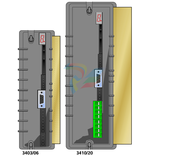
The PC34xxA Series is a new fourth-generation of digital servo amplifiers for controlling Brushless DC and Brush DC servomotors in position, velocity, or current (torque) modes, feedback dependent. Units are available in current ratings of 3, 6, 10 and 20 amps RMS continuous. The product series includes four product families: the PC34xxAd, a Digital servo drive, the Intelligent servo drives PC34xxAi and PC34xxAi-001-xI with extended I/O, the high performance DSP model is a PC34xxAc Centennial servo drive. See section 1.2 Model Designations and Specifications for additional detail. Depending on the model purchased, the PC34xxA product series supports Hall only (Trapezoidal Commutation), Resolver, Comcoder or Hall/Encoder for (Sinusoidal Commutation) or Tach feedback. Each model of the PC34xxA Series utilizes a space vector control algorithm. All modes of operation offer a PID loop-tuning feature to optimize the performance of the selected servomotor. Each PC34xxA unit is a power supply, amplifier, controller and heatsink integrated into a single standalone package. The compact size and integrated design of the PC34xxA amplifier simplifies the installation process and reduces down time should the need for replacement arise. The unit is hardware configured for RS-232 (factory default), RS-422 or RS-485 serial communications with ToolPAC software for configuration, debugging and trouble shooting of the unit. ToolPAC software allows complete configuration and diagnostics of all features in the unit
Fundamentally, a PC34xxA amplifier is a computer that is dedicated to motion control. Like every other computer it has its own operating system, data storage capabilities, data manipulation capabilities. The unit also includes a serial interface for data communications. In addition, its built-in inputs/outputs allow for hard-wired connections for motor feedback and to sensor switches to ensure motion that is in sync with a user’s environment. All PC34xxA Series servo controllers provide the user with the same basic components, including:
• Serial communications port for use with ToolPAC for purposes of trouble shooting and initial drive configuration.
• A graphical user interface program, ToolPAC, provides the user with the tools to quickly and easily configure the PC34xxA to a specific motor and application. ToolPAC provides Wizards for Axis Setup, I/O Configuration, Tuning and is compatible with WIN95/WIN98/NT operating systems.
• System software including commands and parameters that allow you to configure the servo controller to your application, to enter and manipulate data, and to tune the performance of the unit to your application.
• Methods of control include Position, Velocity, and Current (torque) with the ability to accept Step/Dir, Step+/step- and Encoder quadrature in Following mode whereby you are commanding the servo system in a position following mode. Master/slave relationships can be developed from the secondary encoder inputs, providing motion output.
• Distributed Feedback; A mode of operation where a secondary encoder is used to close the Position loop in an application. When using Distributed Feedback you will loose the ability to provide Step/Dir, Step+/Step- or Encoder following as the secondary encoder is wired to these HSI inputs. Thus CAM and Master/Slave relationships are likewise not available.
• The I/O Configuration Wizard provides the user with the tools to configure Hardware interfaces for High-Speed Encoder inputs, CW, CCW, Home inputs, Brake output that allow you to interface to your machinery/equipment.
The PC34xxAi (Intelligent) Series Controllers accept high level commands directly, eliminating the need for a motion controller and can be operated standalone or networked. Each unit has the ability to store and execute motion programs. Additional features available are:
• Stored program mode refers to a method of control where you create and store motion programs on the servo controller system and execute the programs when required. Motion programs provide the user with the ability to perform complex, repetitive functions without having to type each individual command line every time you wish to perform the same function. In this mode you may choose to initiate a program through your communications port or establish a monitor program to allow an input to trigger or begin execution of a particular sequence of commands.
• Networked configuration allows for up to 31 axis from a single PC serial port or similar host device. Multi-axis start and stop, along with on-the-fly speed change, are only a few of the networked features available on these units. The user must request additional documentation to gain a better understanding of the network requirements. The documents listed below, you may log onto ftp site at the address shown below.
• On the PC34xxAi series, up to 100 data points can be entered to define complex SPLINE tables as a function of time or complex CAM tables as a function of the master encoder input. Master/slave (Electronic Gearing) relationships can be developed from the secondary encoder inputs, providing motion output as a RATIO, CAM, or SPLINE.
• The PC34xxAi-001-xI has an additional 16 general-purpose digital inputs and 8 general purpose outputs.
The PC34xxAc (Centennial) Series Servo Controllers are one of the most advanced DSP motion controllers available. It can accept high level commands directly, eliminating the need for a motion controller and can be operated standalone or networked. Each unit has the ability to store and execute motion programs. Additional features available are:
• All modes of operation offer a Real-time Adaptive Tuning feature to optimize the performance of the selected servomotor. This Real-time Adaptive Tuning feature is bi-directional and includes load and inertia estimation and compensation. It also provides an Active Current Loop Compensation gain and phase. Optimal performance can be obtained on systems with varying inertial loads up to 50:1.
• Real-time clock, date and time stamp of fault history.
• Two additional 16-bit analog inputs and two 12-bit analog outputs can be utilized to interface to the user’s environment.
• Advanced mathematical capabilities, 40 bit floating point, LOG functions, and trigonometric functions are available to simplify programming of complex motions.
• Advanced Electronic Gearing functions are available to meet the most demanding applications. Typical applications are conveyors, packaging and folding, labeling and printing, flying knife, shears and too many others to be mentioned.
• Complex SPLINE tables of up to 3000 data points can be entered to define custom motion profiles as a function of time. Complex CAM tables of up to 3000 data points can be entered to define custom motion profiles as a function of the master encoder input or as a function of the Auxiliary PID loop.
• Master/slave relationships can be developed from the secondary encoder inputs, providing motion output as a RATIO or CAM.
• Auxiliary PID loop with 100 microsecond update rate can be utilized in conjunction with the analog inputs, SPLINE, CAM, and master/slave capabilities. Applications such as web-tensioning, pump, and motion profiling can be addressed with ease. PATENT US5357178
PC3400A Family Hardware Reference Manual
The information contained in this document is provided for customer use only. Every effort has been made to ensure the accuracy of this information. However, Pacific Scientific assumes no responsibility for any errors or omissions. The information contained in this document is subject to change without prior notice. Users’ critical evaluation is welcomed to assist in the preparation of future documentation. This document is copyrighted by Pacific Scientific. It is supplied to the user with the understanding that it will not be reproduced, duplicated, or disclosed in whole or in part without the express written permission of Pacific Scientific. Copyright 2001 by Pacific Scientific. All rights reserved. Printed in the United States of America.
-
Beckhoff CX5120-0160 CPU module,
-
Beckhoff CX5120-0150 CPU module
-
Beckhoff CX5120-0143 CPU module
-
Beckhoff CX5120-0142 CPU module
-
Beckhoff CX5120-0141 CPU module, Microsoft Windows 10 IoT Enterprise 2016 LTSB
-
Beckhoff CX5120-0140 CPU module
-
Beckhoff CX5120-0130 CPU module
-
Beckhoff CX5120-0123 CPU module
-
Beckhoff CX5120-0122 CPU module
-
Beckhoff CX5120-0120 CPU module
-
Beckhoff CX5120-0113 CPU module
-
Beckhoff CX5120-0112 CPU module
-
Beckhoff CX5120-0111 CPU module
-
Beckhoff CX5120-0110 CPU module
-
Beckhoff CX5120-0100 CPU module, no operating system
-
Beckhoff C6017-0040 | Fanless ultra-compact Industrial PC
-
Beckhoff C6017 | Fanless ultra-compact Industrial PC
-
Beckhoff C6015-0030 | Fanless ultra-compact Industrial PC
-
Beckhoff C6015-0040 | Fanless ultra-compact Industrial PC
-
Beckhoff C6015 | Fanless ultra-compact Industrial PC
-
Beckhoff CX2500-M510 | Fieldbus master module
-
Beckhoff CX2500-M310 | Fieldbus master module
-
Beckhoff CX2500-B510 | Fieldbus slave module
-
Beckhoff CX2500-B310 | Fieldbus slave module PROFIBUS for CX20xx, CX52x0. CX53x0. CX56x0
-
Beckhoff CX2500-0070 | USB 3.0 module for CX20xx, CX52xx, CX53x0. CX56x0
-
Beckhoff CX2500-0062 | 2.5 Gbit Ethernet module for CX20xx, CX52x0. CX53x0. CX56x0
-
Beckhoff CX2500-1061 | Power over Ethernet module for CX20xx, CX52x0. CX53x0. CX56x0
-
Beckhoff CX2500-1060 | Ethernet module for CX20xx, CX52x0. CX53x0. CX56x0
-
Beckhoff CX2500-0031 | Serial Interface RS485/RS422
-
Beckhoff CX2500-0030 | Serial Interface RS232 for CX20xx, CX52x0. CX53x0. CX56x0
-
Beckhoff CX5230-0195 CPU module
-
Beckhoff CX5230-0190 CPU module
-
Beckhoff CX5230-0175 CPU module,
-
Beckhoff CX5230-0170 CPU module
-
Beckhoff CX5230-0100 CPU module, no operating system, no TwinCAT
-
Beckhoff CU8130-0240 | UPS modul, battery-backed
-
Beckhoff CU8130-0120 | UPS module, battery-backed
-
Beckhoff CU8110-0120 | UPS module, capacitive
-
Beckhoff CU8110-0060 | UPS module, capacitive
-
Beckhoff CX5130-0195 CPU module
-
Beckhoff CX5130-0190 CPU module
-
Beckhoff CX5130-0185 CPU module
-
Beckhoff CX5130-0170 CPU module
-
Beckhoff CX5130-0163 CPU module, Microsoft Windows 10 IoT Enterprise 2019 LTSC, 32 bit
-
Beckhoff CX5130-0162 CPU module
-
Beckhoff CX5130-0161 CPU module
-
Beckhoff CX5130-0160 CPU module
-
Beckhoff CX5130-0155 CPU module
-
Beckhoff CX5130-0150 CPU module
-
Beckhoff CX5130-0143 CPU module
-
Beckhoff CX5130-0142 CPU module
-
Beckhoff CX5130-0140 CPU module
-
Beckhoff CX5130-0135 CPU module
-
Beckhoff CX5130-0130 CPU module
-
Beckhoff CX5130-0125 CPU module
-
Beckhoff CX5130-0123 CPU module
-
Beckhoff CX5130-0122 CPU module
-
Beckhoff CX5130-0121 CPU module
-
Beckhoff CX5130-0115 CPU module,
-
Beckhoff CX5130-0113 CPU module
-
Beckhoff CX5130-0112 CPU module
-
Beckhoff CX5130-0111 CPU module
-
Beckhoff CX5130-0110 CPU module, Microsoft Windows Embedded Compact 7. no TwinCAT
-
Beckhoff CX5130-0100 CPU module, no operating system, no TwinCAT
-
DEIF FAS-113DG Synchronisation & circuit breaker closing
-
DEIF FAS-115DG Synchronisation & circuit breaker closing
-
DEIF HAS-111DG Synchronisation & circuit breaker closing
-
DEIF LSU-122DG Load sharing, paralleling & operation
-
DEIF LSU-114DG Load sharing, paralleling & operation
-
DEIF LSU-113DG Load sharing, paralleling & operation
-
DEIF LSU-112DG Load sharing, paralleling & operation
-
DEIF RMF-112D Frequency relay
-
DEIF RMC-142D Current relay
-
DEIF RMC-132D Current relay
-
DEIF RMC-131D Current relay
-
DEIF RMC-122D Current relay
-
DEIF RMC-121D Current relay
-
DEIF RMC-111D Current relay
-
DEIF MVR-V211 Busbar Protection
-
DEIF MVR-T257 Transformer Differential Protection
-
DEIF MVR-T256 Transformer Differential Protection
-
DEIF MVR-T216 Transformer Differential Protection
-
DEIF MVR-T215 Transformer Protection
-
DEIF MVR-M257 Motor Differential Protection
-
DEIF MVR-M255 Motor Protection
-
DEIF MVR-M215 Motor Protection
-
DEIF MVR-M210 Motor Protection
-
DEIF MVR-G257 Generator Differential Protection
-
DEIF MVR-G215 Generator Protection
-
DEIF MVR-F255 Directional Feeder Protection
-
DEIF MVR-F215 Directional Feeder Protection
-
DEIF MVR-F210 Feeder Protection
-
DEIF MVR-F205 Directional Feeder Protection
-
DEIF MVR-F201 Basic Feeder Protection
-
DEIF MVR-200 series Medium Voltage Relay
-
DEIF MDR-2 Multi-differential relay
-
DEIF LMR-122D Loss of mains relay
-
DEIF LMR-111D Loss of mains relay
-
DEIF APU-4 Advanced G59 and G99 protection unit
-
DEIF iE 650 PLC - The most robust programmable automation controller available
-
DEIF iE 350 PLC - Programmable Automation PLC Controller
-
DEIF iE 250 PLC Versatile and modular intelligent energy PLC controller
-
DEIF PPM-3 EDG Protection and Power Management
-
DEIF AGC 3X 4198000234E AUTOMATIC GENSET CONTROLLER
-
SAUTER ASF123 Damper actuator with spring return
-
SAUTER ASF122 Damper actuator with spring return
-
SAUTER ASF113F122 Damper actuator with spring return
-
SAUTER ASF113F120 Damper actuator with spring return
-
SAUTER ASF112F122 Damper actuator with spring return
-
SAUTER ASF112F120 Damper actuator with spring return
-
SAUTER ASM 124/134 series - ASM134F130 Damper actuator
-
SAUTER ASM 124/134 series - ASM134SF132 Damper actuator
-
SAUTER ASM 124/134 series - ASM124SF132 Damper actuator
-
SAUTER ASM 124/134 series - ASM124F122 Damper actuator
-
SAUTER ASM 124/134 series - ASM124F120 Damper actuator
-
SAUTER Valve actuator ASM 105S/115S series ASM115SF152
-
SAUTER Valve actuator ASM 105S/115S series ASM105SF152
-
SAUTER Valve actuator ASM 105S/115S series ASM115SF132
-
SAUTER Valve actuator ASM 105/115 series ASM105SF132
-
SAUTER Valve actuator ASM 105/115 series ASM115F122
-
SAUTER Valve actuator ASM 105/115 series ASM115F120
-
SAUTER Valve actuator ASM 105/115 series ASM105F122
-
SAUTER Valve actuator ASM 105/115 series ASM105F120
-
SAUTER Valve actuator ASM 105/115 series ASM105F10
-
SAUTER AKF113S Rotating actuator AKF 112/113 series
-
SAUTER AKF113F122 Rotating actuator AKF 112/113 series
-
SAUTER AKF113F120 Rotating actuator AKF 112/113 series
-
SAUTER AKF112F122 Rotating actuator AKF 112/113 series

Add: High-tech Software Park, Xiamen City, Fujian Province
Mobile: +86-17750019513(WhatsApp)
Email: yy4291644@gmail.com
Website: https://www.abb-sis.com
.jpg)
.jpg)
.jpg)
.jpg)
.jpg)
.jpg)

-
Beckhoff CX5120-0160 CPU module,
-
Beckhoff CX5120-0150 CPU module
-
Beckhoff CX5120-0143 CPU module
-
Beckhoff CX5120-0142 CPU module
-
Beckhoff CX5120-0141 CPU module, Microsoft Windows 10 IoT Enterprise 2016 LTSB
