

Pressductor Pillowblock Load Cells Vertical Measuring PFCL 201 User manual
USE OF SYMBOLS
This publication includes the following symbols with information regarding safety or other important information:
CAUTION Caution icon indicates important information. Risk of damage to equipment, property or software.
DANGER Danger icon indicates a hazard which could result in personal injury or even death.
ELECTRICAL Electrical warning icon indicates the presence of a hazard which could result in electrical shock.
ESD ESD icon indicates that electrostatic discharge precautions are needed.
Information Information icon alerts the reader to relevant facts and conditions.
Tip Tip icon advise how to design your product or how to use a certain function.
NOTICE
The information in this document is subject to change without notice and should not be construed as a commitment by ABB
AB. ABB AB assumes no responsibility for any errors that may appear in this document.
In no event shall ABB AB be liable for direct, indirect, special, incidental or consequential damages of any nature or kind arising from the use of this document, nor shall ABB AB be liable for incidental or consequential damages arising from use of any software or hardware described in this document.
This document and parts thereof must not be reproduced or copied without ABB AB’s written permission, and the contents thereof must not be imparted to a third party nor be used for any unauthorized purpose. The software described in this document is furnished under a license and may be used, copied, or disclosed only in accord ance with the terms of such license.
Description
General
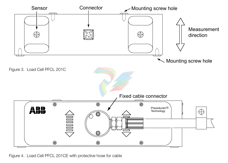
The load cell is machined from a single piece of stainless steel. The sensors are machined directly in the piece of steel and are positioned so that they are sensitive to force in the direction of meas urement and insensitive in other directions.
The load cell is mounted on a base with four screws, and the bearing housing is mounted on top of the load cell with four screws.
Every load cell comes calibrated and temperature compensated.
The load cells PFCL 201C/201CE/201CD are available in four measurement ranges, all variants have the same external dimensions.
The load cell PFCL 201C is equipped with a connector for the pluggable connection cable. The load cell PFCL 201CE has a fixed connection cable with protective hose. The load cell PFCL 201CD is provided with an acid-proof cable gland with a fixed PTFE- insulated connection cable.
Definitions
Nominal load
Nominal load, Fnom, is the maximum load in the measurement direction for which the load cell is dimensioned to measure within the specified accuracy class. The load cell is calibrated up to Fnom.
Sensitivity
Sensitivity is defined as the difference in output values between nominal load and zero load.
Accuracy and Accuracy Class
Accuracy class is defined as the maximum deviation, and is expressed as a percentage of the sen sitivity at nominal load. This includes linearity deviation, hysteresis and repeatability error.
Linearity Deviation
Linearity deviation is the maximum deviation from a straight line drawn between the output values at zero load and nominal load. Linearity deviation is related to the sensitivity.
Hysteresis
Hysteresis is the maximum difference in the output signal at the same load during a cycle from zero load to nominal load and back to zero load, related to the sensitivity at nominal load. The hysteresis of a Pressductor transducer is proportional to the load cycle.
Repeatability error
Repeatability error is defined as the maximum deviation between repeated readings under identical conditions. It is expressed as a percentage of the sensitivity at nominal load.
Compensated temperature range
The temperature drifts of the load cell have been compensated for in certain temperature ranges. That is the temperature range within which the specified permitted temperature drifts (i.e. zero point and sensitivity drifts) of the load cell are maintained.
Working temperature range
Working temperature range is the temperature range within which the load cell can operate within a specified accuracy. The maximum permitted temperature drifts (i.e. zero point and sensitivity drifts) of the load cell are not necessarily maintained in the whole working temperature range.
Storage temperature range
Storage temperature range is the temperature range within which the load cell can be stored.
Zero point drift with temperature
Zero point drift is defined as the signal change with temperature, related to the sensitivity, when there is zero load on the load cell.
Sensitivity drift with temperature
Sensitivity drift is defined as the signal change with temperature at nominal load, related to the sen sitivity, excluding the zero point drift.
Compression
Compression is the total reduction in the height of the load cell when the load is increased from zero to the nominal value.
Measuring principle of the sensor
The measuring principle of the sensor is based on the Pressductor® technology and the fact that
the permeability of a magnetic material changes under mechanical stress.
The sensor is a membrane machined in the load cell. Primary and secondary windings are wound through four holes in the load cell so that they cross at right angles.
The primary winding is supplied with an alternating current which creates a magnetic field around the primary winding. Since the two windings are at right angles to each other, there will be no mag netic field around the secondary winding, as long as there is no load on the sensor.
When the sensor is subjected to a mechanical force in the direction of measurement, the propaga tion of the magnetic field changes so that it surrounds the secondary winding, inducing an alternat ing voltage in that winding.
The control unit converts this alternating voltage into a DC voltage proportional to the applied force. If the measurement force changes direction, the sensor signal changes also polarity.
Mounting Arrangement
When choosing a mounting arrangement it is important to remember to position the load cell in a
direction that gives sufficient measuring force (FR) to achieve the highest possible accuracy.
The load cell has no particular correct orientation; it is positioned in the orientation best suited for the application, bearing in mind the positions of the screw holes. The load cell can also be installed with the roll suspended under the load cell.
The load cell has the same sensitivity in both tension and compression, so the load cell can be installed in the easiest manner.
Typical mounting arrangements are horizontal and inclined mounting.
Coordinate System
A coordinate system is defined for the load cell. This is used in force calculations to derive force components in the load cell principal directions.
Where direction designations R, V and A are recognized as suffixes for force components, F, this represents the force component in the respective direction. The suffix R may be omitted, when measuring direction is implied by the context.
Horizontal Mounting In the majority of cases horizontal mounting is the most obvious and simplest solution. Stand, mounting surface and shims (if required) are simple and cheap to make. When calculating the force, the equations below must be used:
FR = T × (sin α + sin β) FRT = Tare FRtot = FR + FRT = T × (sin α + sin β) + Tare FV = T × (cos β - cos α) FVT = 0 FVtot = FV + FVT = T × (cos β - cos α) + 0 = T × (cos β - cos α) where: T = Strip tension
FR = Force component from strip tension in measurement direction, R FRT = Force component from Tare in measurement direction, R FRtot = Total force in measurement direction, R FV = Force component from strip tension in transverse direction, V FVT = Force component from Tare in transverse direction, V FVtot = Total force in transverse direction, V Tare = Force due to tare weight α = Deflection angle on one side of the roll relative the horizontal plane β = Deflection angle on the other side of the roll relative the horizontal plane
Inclined Mounting
Inclined mounting means arrangements in which the load cell is inclined relative to the horizontal
plane. In some cases this is the only option.
When calculating the force, the equations below must be used:
FR = T × [sin (α - γ) + sin (β + γ)] FRT = Tare × cos γ FRtot = FR + FRT = T × [sin (α - γ) + sin (β + γ)] + Tare × cos γ FV = T × [cos (β + γ) - cos (α - γ)] FVT = - Tare × sin γ FVtot = FV + FVT = T × [cos (β + γ) - cos (α - γ)] - Tare × sin γ γ = 90° - φ
where:
T = Strip tension FR = Force component from strip tension in measurement direction, R FRT = Force component from Tare in measurement direction, R FRtot = Total force in measurement direction, R FV = Force component from strip tension in transverse direction, V FVT = Force component from Tare in transverse direction, V FVtot = Total force in transverse direction, V Tare = Force due to tare weight α = Deflection angle on one side of the roll relative the horizontal plane β = Deflection angle on the other side of the roll relative the horizontal plane φ= Angle for measurement direction relative the horizontal plane γ = Angle for load cell mounting surface relative the horizontal plane
The load cell is supplied with a 0.5 A, 330 Hz alternating current. The secondary signal is calibrated for the correct sensitivity with a voltage divider R1 - R2, and temperature compensation is provided by thermistors T. All impedances on the secondary side are relatively low. The output impedance is typically 9-12 Ω , which helps to suppress interference.
General
The equipment is a precision instrument which, although intended for severe operating conditions,
must be handled with care. The load cells should not be unpacked until it is time for installation.
To achieve the specified accuracy, the best possible reliability and long-term stability, the load cells must be installed in accordance with the instructions below. See also
• The foundation for the load cell must be made as stable as possible. A resilient stand lowers the critical frequency of the measuring roll and bearing arrangement.
• The surfaces closest to the load cell, and other surfaces that affect the fit, must be machined f lat to within 0.05 mm.
• There must not be any shims immediately above or below the load cell, as this may adversely affect the flatness. Instead, shims may be placed between the adapter plate and the foundation or between the adapter plate and the bearing housing.
• The screws that secure the load cell must be tightened with a torque wrench.
• The bearing arrangement for the measuring roll must be designed to allow axial expansion of the roll with changes in temperature.
• Any drive to the roll must be applied in such a way that interfering forces from the drive are kept to a minimum.
• The measuring roll must be dynamically balanced.
• The mounting surfaces of the load cells must be on the same height and parallel with the measuring roll.
• In a corrosive environment, galvanic corrosion may occur between the load cell, galvanized screws and adapter plates. This makes it necessary to use stainless steel screws and adapter plates of stainless steel or equivalent. See adapter plates in
Unpacking
When the equipment arrives, check against the delivery document. Inform ABB of any complaint,
so that errors can be corrected immediately and delays avoided.
Preparations
Prepare the installation in good time by checking that the necessary documents and material are
available, as follows:
• Installation drawings and this manual.
• Standard tools, torque wrench and instruments.
• Rust protection, if additional protection is to be given to machined surfaces. Choose TEC TYL 511 (Valvoline) or FERRYL (104), for example.
• Load cells, adapter plates, bearing housings, etc.
• Locking fluid (medium strength) to lock mounting screws.
• Screws as listed in Table 3. page 19 and Table 4. page 19 to secure the load cell, and other screws for bearing housings etc.
Mounting
The instructions below apply to a typical mounting arrangement. Variations may be allowed, provi
ded that the requirements of 3.1 General are complied with.
Clean the foundation and other mounting surfaces.
2. Fit the lower adapter plate to the load cell. Tighten the screws to the torque stated in Table
3. page 19 or Table 4. page 19. 3. Fit the load cell and the lower adapter plate to the foundation, but do not fully tighten the screws.
4. Fit the upper adapter plate to the load cell, tighten to the torque stated in Table 3. page 19 or Table 4. page 19.
5. Fit the bearing housing and the roll to the upper adapter plate, but do not fully tighten the screws.
6. Adjust the load cells so that they are in parallel with each other and in line with the axial direction of the roll. Torque tighten the foundation screws.
7. Adjust the roll so that it is at right angles to the longitudinal direction of the load cells.Torque tighten the screws in the upper adapter plate.
8. Apply rust protection to any machined surfaces that are not rust proof.
Cabling for Load Cell PFCL 201CE
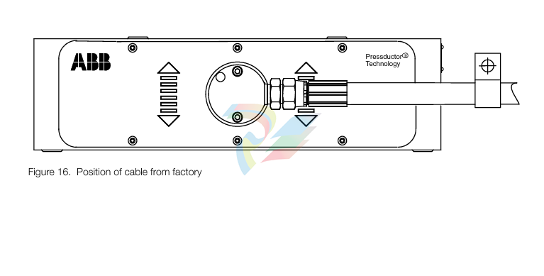
Cabling with protective hose shall be mounted so that the forces related to the weight of the cable/ hose do not act in the measuring direction of the load cell. A cable clamp is therefore necessary. If the load cell is prevented from movement in the measuring direction- it will shunt force, and the measured force will differ from the actual.
The favourable direction of the cable/hose is the horizontal direction to the left or right as indicated in Figure 16. Position of cable from factory page 20. This as possible forces in the longitudinal direction of the cable/hose due to temperature, will act perpendicular to the measuring direction of the load cell (the direction in which the load cell is insensitive to loads).
For achievable cable directions, see Figure 17. Possible directions of cable for PFCL 201CE page 21. The direction of the cable and protective hose can be changed by unscrewing the two screws in the connection box and turning the cable to a suitable direction. Make sure to re-install the screws in the connection box.
General
The actual procedure for commissioning a load cell is simple, provided that the load cells and
cables have been properly installed. Commissioning of the control unit is described in the relevant
chapter of the control unit manual.
Check the following:
• that the load cells have been correctly installed and aligned
• that all screws have been tightened to the correct torque
• that all cables are correctly installed and connected
• that all connectors are plugged in
Preparatory Calculations
To be able to set the correct measuring range, the measurement force per load cell FR/2 at maxi
mum tension T must be calculated. Each load cell is subjected to half the total measurement force
FR. This calculation must be done before commissioning can begin. Calculation of FR is described
in 2.5 Mounting Arrangement.
Maintenance
General
Strip Tensiometer Systems with Pressductor® load cells are extremely reliable and do not require daily servicing. As a preventive measure, checks should be done periodically on all parts subject to mechanical wear.
Preventive Maintenance
Check mounting screws and tighten if necessary.
The gaps between load cell and plates should be checked to ensure that they do not get clogged with dirt, causing shunt force past the load cell. Clean the gaps with compressed air if necessary. The cable between the load cell and the junction box is subjected to possible damage and should be checked and replaced if necessary.
Spare Parts
Users are recommended to keep the following spare parts in stock:
• One load cell of correct type and size.
• One connector complete with cable (for PFCL 201C)
Table 5 Ordering numbers for Load Cell PFCL 201
Load cell PFCL 201C 5,0 3BSE027070R5
Load cell PFCL 201C 10,0 3BSE027070R10
Load cell PFCL 201C 20,0 3BSE027070R20
Load cell PFCL 201C 50,0 3BSE027070R50
Load cell PFCL 201CE 5,0 3BSE027062R5
Load cell PFCL 201CE 10,0 3BSE027062R10
Load cell PFCL 201CE 20,0 3BSE027062R20
Load cell PFCL 201CE 50,0 3BSE027062R50
Load cell PFCL 201CD 5,0 3BSE029774R5
Load cell PFCL 201CD 10,0 3BSE029774R10
Load cell PFCL 201CD 20,0 3BSE029774R20
Load cell PFCL 201CD 50,0 3BSE029774R50
General
It is important to be thoroughly familiar with the description of operation in
2 Description before starting fault tracing.
Interchangeability
The load cells are factory calibrated and can be replaced directly with another load cell of the same
type. The only adjustment required after load cell replacement is zero adjustment in the control
unit.
Fault Tracing Procedure
The measuring equipment can be divided into four parts:
• The mechanical installation.
• The load cell.
• The junction boxes and the cabling.
• The control unit (see the control unit manual).
The fault symptoms indicate in which part the fault lies.
• Faults in the mechanical installation often result in an unstable zero point or incorrect sensi tivity. If a fault follows something else in the process, such as temperature, or can be linked to a particular operation, it probably originates from something in the mechanical installation.
• Load cells are extremely robust and can withstand ten times their nominal load in the meas uring direction. If a load cell has nevertheless been so overloaded that its data have been altered, this is probably due to an event in the mill, such as strip breakage. On excessive overload the first thing that happens is that the zero point shifts.
• Problems such as interference or unstable zero point may be caused by wiring faults. Some malfunctions may be due to the proximity of cables that cause interference. Incorrect instal lation, such as imbalance in a cable or screens earthed at more than one end may cause the zero point to become unstable. Cables are subject to mechanical wear, and should be checked regularly. The junction box should also be checked, especially if it is subject to vibration.
• A fault in the control unit usually causes intermittent loss of a function. It is unusual for the control unit to cause stability problems. Faults in connected units may affect the operation of the control unit. For further details see the control unit manual.
Fault Tracing in the Mechanical Installation
There are a number of parts in the mechanical arrangement that can cause faults. The extent to
which these faults are repeatable differs. Possible causes fall into the following groups.
• Defective mounting surface, stand or adapter plates.
• Force shunting.
• Insufficient mounting of load cell and adapter plates.
• Rolls and bearings. • Driven roll.
Defective Mounting Surface, Support or Adapter Plates
An unmachined or poorly machined mounting surface, which is uneven, may cause bending or
twisting of the load cell. This may result in instability of the zero point.
Force Shunting
Force shunting means that some of the force is diverted past the load cell. This may be caused by some kind of obstruction to the force through the load cell. The connecting cables, for example, have been incorrectly installed and are preventing movement. Another possible cause is that the roll is not free to move in the direction of measurement, possibly because something is mounted too close to a bearing housing, or because an object has worked loose and become trapped between the bearing housing and adjacent parts.
Force shunting causes the strip tension indication to be lower than the actual strip tension.
Fastening of Load cell and Adapter Plates
Screw joints that have not been properly tightened or have lost their pre-tightening force, cause sliding at the mating surfaces. Fastening of the load cell is especially critical. If a load cell is not properly secured, the zero point will be unstable. Sliding between other surfaces may cause the same symptoms.
Rolls and Bearings
An incorrectly designed bearing arrangement may give rise to high axial forces. The roll should be f ixed at one end and free at the other. If both ends are fixed, there will be a high axial (thrust) force due to expansion of the shaft with rising temperature. Even a correctly designed bearing arrangement may deteriorate with time; bearings become worn, and so on. This may give similar symptoms, such as slow zero point drift between cold and hot machine, or sudden jumps in the signal.
Driven Roll
A source of error that is seldom suspected is the roll itself. The effect is especially critical when measuring forces on the load cell are relatively low. Long drive shafts with their associated universal joints may cause unstable signals if they are not properly maintained. It is important to lubricate universal joints. Longitudinal expansion of the drive shaft should also be taken into account. Since such expansion is often taken up by splines, these must also be lubricated. The symptoms are instability of the signal, for instance jumps in the signal during slow running.
Fault Tracing of Load Cells, Junction Boxes and wiring
The load cell is very robust and can withstand high overloads. The data of a Pressductor load cell
does not change slowly, but in steps, usually in connection with an event in the mill. Excessive
overloading usually results in permanent shifting of the zero point.
Poor contact in the junction box causes intermittent faults. Both sensitivity and zero point may vary. Check all screw terminals. Do not use pins crimped to the connecting wires, as these often work loose after a time.
The cabling, especially the cable to the load cell, is the part that is most exposed to damage.
Since the resistance of the load cell windings is low, it is easy to check the load cells and cabling from the control unit.
Typical readings are 2 Ω for the resistance of the primary winding and 9-12 Ω for the output impedance of the secondary winding.
Insulation faults in the cabling or the load cell may cause incorrect sensitivity or unstable zero point. When the load cell circuits have been isolated from earth and from the control unit at the discon nectable terminals, it is easy to measure the insulation from the control unit. If the cables are not routed correctly, they may pick up interference from other cables.
For circuit diagram applications, see the manual for the applicable control unit: Millmate Strip Tension Systems with Millmate Controller 400, 3BSE023139Rxxxx Web Tension Systems with Tension Electronics PFEA 111/112, 3BSE029380Rxxxx Web Tension Systems with Tension Electronics PFEA 113, 3BSE029382Rxxxx

-
Adlink NuPRO-E42 51-41808-0A30 Industrial Motherboard
-
ADLINK IH61-AA400-A4A1E (IMB-M40H) Industrial Motherboard
-
ADLINK PCIe-GIE64+ GigE Vision Frame Grabber Card
-
ADLINK MXC-6322D(G) Industrial Fanless Computer working
-
ADLINK CPCI-7300 32-CH 80 MB/s High-Speed Digital I/O Module
-
Adlink cPCI-8168 Advanced 6U Compact PCI 8-Axis Motion Controller
-
Adlink VME CPU Board cPCI-6626/2710/M4G
-
ADLINK cPCI-R6200 high-performance 6U CompactPCI Rear Transition Module (RTM)
-
Adlink cPCI-7248 48-CH Opto-22 Compatible Digital I/O Module
-
ADLINK DLAP-211-JNX/DLAP-211-JT2/ DLAP-211-Nan
-
ADLINK cPCI-3544 4-Port RS-422/485 Isolated Serial Communications Card
-
Hirschmann MSP30-16040SCZ999HHE2A Manage the basic unit of the industrial DIN-Rail switch
-
Hirschmann MSP30-16040SCY999HHE2A
-
Hirschmann RS20-0400S2S2SDAEHC09.0.00 Management-type industrial fast Ethernet switch
-
Hirschmann Belden OCTOPUS OS20-002800T5T5T5-TBBY999GMSE3S Manageable industrial Ethernet switch
-
HIRSCHMANN OS20-000800T5T5T5-TBBU999H5SE2S
-
HIRSCHMANN RS20-0800M4M4SDAEHC09.0.14 industrial switch
-
Hirschmann RS20-0800T1T1SDAUHC RS20-0800T1T1SDAE
-
Hirschmann MSM20-M2M2M2M2SY9HH9E99.9 Fast Ethernet Media Module
-
HIRSCHMANN MAR1040-4C4C4C4C9999SMMHPHH Managed Etherne
-
HIRSCHMANN MAR1040-4C4C4C4C9999SMMHPHH Managed Etherne
-
HIRSCHMANN MAR1040-4C4C4C4C9999SM9HRHH Managed Etherne
-
HIRSCHMANN MAR1040-4C4C4C4C9999SM9HPHH05.1.00 industrial switch
-
HIRSCHMANN MM20-P9P9M2T1SAHH Fast Ethernet media module
-
HIRSCHMANN MM20-P9T1T1T1SAHH hot-swappable hybrid media module
-
HIRSCHMANN MM20-Z6Z6T1M2SAHH Fast Ethernet media module
-
HIRSCHMANN MM20-Z6M2M2T1SAHH Fast Ethernet media module
-
HIRSCHMANN MM20-Z6Z6Z6T1SAHH media module.
-
HIRSCHMANN MM20-Z6T1T1T1EBH Fast Ethernet media card.
-
Hirschmann MM20-Z6T1T1T1SAHH Hot-swappable fast Ethernet media module
-
Hirschmann MM20-Z6Z6M2M2EBH media module
-
HIRSCHMANN MM20-Z6Z6T1T1SZHH Technical Datasheet & SEO Guide
-
HIRSCHMANN MM20-Z6Z6T1T1EBH Technical Datasheet & Overview
-
HIRSCHMANN MM20-Z6Z6Z6Z6SZHH Media Module
-
HIRSCHMANN MM20-M4M2M2T1SAHH Media Module
-
HIRSCHMANN MM20-M4T1M2T1SAHH Media Module
-
HIRSCHMANN MM20-M2M2T1T1EBH Media Module
-
HIRSCHMANN MM20-M2M2T1T1SAHH Media Module
-
HIRSCHMANN MM20-M2T1T1T1TAHH Media Module
-
HIRSCHMANN MM20-M2T1T1T1EBH Media Module
-
HIRSCHMANN MM20-M2T1T1T1SAHH Media Module
-
HIRSCHMANN MM20-M2T1T1T1SAHH Media Module
-
HIRSCHMANN MM20-M2T1T1T1SAHH Media Module
-
HIRSCHMANN MM20-M2T1T1T1SAHH Media Module
-
HIRSCHMANN MM20-M2M2M2M2EBH Industrial Ethernet Media Module
-
HIRSCHMANN RS20-1600S2S2SDAEHH09.0.14 Ethernet switch
-
HIRSCHMANN MSM20-M2M2T1T1SY9HH9E99.9.99
-
HIRSCHMANN MSM20-M2M2M2M2SY9HH9E Ethernet media modul
-
HIRSCHMANN SPIDER-PL-20-05T1999999TWVHHHH Industrial Ethernet Rail Switch
-
Hirschmann SPIDER-PL-20-07T1M2M299TWVHHHH Industrial ETHERNET Rail Switch
-
Hirschmann (Belden) RS20-1600M2M2SDAEHC09.1.00 DIN-rail managed industrial Fast Ethernet switch
-
Hirschmann (Belden) RS30-1602O6O6TDAPHC09.1.00 DIN-rail managed industrial Ethernet switch
-
Hirschmann RS30-2402O6O6SDAP Ethernet switch
-
Hirschmann (Belden) RS30-2402O6T1SDAPHH09.0.13 DIN-rail industrial Ethernet switch
-
Hirschmann (Belden) RS30-2402O6T1SDAPHH09.0.13 DIN-rail industrial Ethernet switch
-
Hirschmann (Belden) SPIDER-PL-20-04T1S29999TY9HHHH Ethernet DIN-rail switch
-
HIRSCHMANN RS20-1600T1T1SDAUHX Switch
-
HIRSCHMANN BRS42-0012OOOO-SPCZ99HHSES industrial switch
-
Hirschmann RS20-0800S2S2TDHPHH09.0.14 Fast Ethernet DIN rail switch.
-
HIRSCHMANN MM20-Z6Z6M2M2SAHH Hybrid Fast Ethernet Media Module
-
HIRSCHMANN MM20-Z6Z6T1T1SAHH hot-swappable hybrid Fast Ethernet Media Module
-
HIRSCHMANN MM20-P9P9T1T1SAHH Hybrid Fast Ethernet Media Module
-
HIRSCHMANN MM20-M4T1T1T1SAHH Hybrid Fast Ethernet Media Module
-
HIRSCHMANN MM20-M4M4T1T1SAHH Hybrid Fast Ethernet Media Module
-
HIRSCHMANN MM20-M2M2M2M2SZHH Ethernet media module
-
HIRSCHMANN MM20-M2M2M2M2SAHH Ethernet media module
-
HIRSCHMANN MM20-T1T1T1T1EBH 4-port Fast Ethernet Copper Cable Media Module
-
HIRSCHMANN MM20-T1T1T1T1SAHH 4-port Fast Ethernet Copper Cable Media Module
-
HIRSCHMANN MM20-Z6Z6EBH Hot-swappable fast Ethernet media module
-
HIRSCHMANN MM20-Z6Z6SAHH Ethernet media module
-
HIRSCHMANN MM20-Z6Z6Z6Z6EBH Industrial Media Module
-
MSM40-T1T1T1TZ9HH9E99.9.99 HIRSCHMANN Switch
-
HIRSCHMANN MS20-0800SAAEHC / MS20-0800SAAEHC0 8-port modular Layer 2 management Ethernet switch
-
Hirschmann RSPM20-4T14T1SZ9HHS9 Switch RSPM20-4T14T1SZ9HHS9
-
HIRSCHMANN RS20-1600M2M2SDAEHH09.1. RS20/30/40 Managed Switch configurator
-
HIRSCHMANN RS20-1600M2M2SDAEHX09.0.00 Ethernet switch
-
HIRSCHMANN BELDEN SPIDER-PL-20-07T1M2M299TY9HHHH / SPIDERPL2007T1M2M299TY9HHHH
-
HIRSCHMANN MM3-1FXS2/3TX1 Switching Board Module
-
HIRSCHMANN RSPE30-24044O7T99-SCCV999HHSI2SXX.X.XX Switch
-
HIRSCHMANN RSPE30-24044O7T99-ECCP999HHSE2A08.1.00 Industrial-grade fanless management-type Ethernet switch
-
HIRSCHMANN RS30-1602OOZZSDAEHC09.1.00 DIN-rail-mounted managed Layer 2 Ethernet switch
-
HIRSCHMANN MACH104-20TX-F Managed 24-port Full Gigabit 19" Switch
-
HIRSCHMANN Switch RS20-0800M4M4SDAE
-
Hirschmann RS30-1602O6O6SDAEHH09.1. Management-type Ethernet switch
-
Hirschmann RS30-1602OOZZSDAEHC09.0.10 Open rack-style Ethernet switch
-
HIRSCHMANN RSPE30-24044O7T99-SCCV999HHSI2SXX.X.XX High-Availability Seamless Redundancy
-
HIRSCHMANN RSPE30-24044O7T99-SCCZ999HHSE2A DIN-rail Ethernet switch
-
HIRSCHMANN MM2-4TX1-EEC switch
-
HIRSCHMANN MSM40-T1T1T1T1TZ9HH9E99.9.99 Module
-
HIRSCHMANN RS20 Rail Switch RS20-0400S4T1SDAEHC07.1.01
-
HIRSCHMANN M4-FAST8-SFP Fast Ethernet media module
-
HIRSCHMANN RS20-0400M2T1SDAP Managed Fast-Ethernet-Switch
-
HIRSCHMANN BELDEN SPIDER II 8TX/1FX EEC Industrial Ethernet Rail Switch
-
HIRSCHMANN MM3-2FXS2/2TX1
-
HIRSCHMANN RS2-4TX/1FX EEC Industrial Ethernet Rail Switch 2
-
RS30-0802O6O6SDAEHC09.0.10 HIRSCHMANN Switch
-
HIRSCHMANN m4-8TP-RJ45 Ethernet Media Module
-
HIRSCHMANN MSP30-24040SCZ9URHHE3A switch
-
Hirschmann rack MS30-1602SAAPHC
-
HIRSCHMANN RS2-FX/FX Industrial Switch Module
-
Rs1txfx - Hirschmann - Rs1-Tx/Fx Rail Switch
-
RS20-0800S2S2SDAEHC09.1.00 HIRSCHMANN Commutator
-
Hirschmann EAGLE20 TX/TX Industrial Security Router
-
Hirschmann SPIDER-SL-20-04T1S29999SY9HHHH Industrial Switch
-
HIRSCHMANN MAR1040-4C4C4C4C9999SMMHRHHXX.X. Gigabit Ethernet Switch configurator
-
Hirschmann MAR1040 Industrial Switch
-
HIRSCHMANN BELDEN RS30-1602O6O6SDAE
-
Hirschmann RS20-1600M2M2SDAUHC Ethernet DIN rail switch
-
HIRSCHMANN OCTOPUS24M industrial switch
-
HIRSCHMANN RS20-1600T1T1SDAE Management-type Ethernet switch
-
HIRSCHMANN RS20-1600T1T1SDAUHH industrial switch
-
HIRSCHMANN RS20-0800M2M2SDAPHC09.0.04 switch
-
Hirschmann MR 8-03 24V DC Industrial Modular Bridge/Router
-
HIRSCHMANN RS20-0400M2T1SDAPHC08.0.01 Managed Switch
-
MACH1130 Hirschmann Industrial Switch
-
HIRSCHMANN 943824-002 SPIDER 5TX Industrial Ethernet Switch
-
HIRSCHMANN RS30-0802O6O6SDAEHC09.1.00 Managed Industrial Switch
-
HIRSCHMANN RS20-0400M2M2TDAEHC04.0.01 Industrial Switch
-
HIRSCHMANN BRS20-0600Z6Z6-STCZ99HHSES Industrial Switch
-
HIRSCHMANN MACH104-20TX-FR-L3P Industrial Ethernet Switch
-
HIRSCHMANN RS40-0009CCCCEDBPHH06.0.01 Industrial Switch
-
HIRSCHMANN RS2-3TX/2FX EEC Industrial Ethernet Switch
-
Hirschmann MACH 1020/1030 Fast/Gigabit Rack Mount Switches
-
HIRSCHMANN RS20-0800M2M2SDAPHC09.0.14 Industrial Switch
-
HIRSCHMANN RS20-1600T1T1SDAEHC09.0.04 Industrial Switch
-
HIRSCHMANN RSB20-0800T1T1EAABHH Industrial Switch
-
HIRSCHMANN MACH4002-48+4G-L3E Industrial Backbone Switch
-
HIRSCHMANN RS20-0400S2T1SDAE Industrial Managed Switch
Add: High-tech Software Park, Xiamen City, Fujian Province
Mobile: +86-17750019513(WhatsApp)
Email: yy4291644@gmail.com
Website: https://www.abb-sis.com
.jpg)
.jpg)
.jpg)
.jpg)
.jpg)
.jpg)

-
Adlink NuPRO-E42 51-41808-0A30 Industrial Motherboard
-
ADLINK IH61-AA400-A4A1E (IMB-M40H) Industrial Motherboard
-
ADLINK PCIe-GIE64+ GigE Vision Frame Grabber Card
-
ADLINK MXC-6322D(G) Industrial Fanless Computer working
-
ADLINK CPCI-7300 32-CH 80 MB/s High-Speed Digital I/O Module
