

610 serie ABB Feeder Protection REF610 Product Guide
Description
REF610 is a feeder protection relay for protection, measuring and supervision of utility and industrial distribution power systems. REF610 is a member of ABB’s Relion® protection and control product family and part of its 610 product series. The 610 series includes protection relays for feeder protection, motor protection and general system voltage supervision. The plug-in design of the 610 series protection relays facilitates the commissioning of the switchgear and enables fast and safe insertion and withdrawal of relay plug-in units.
The protection relay is primarily targeted at the protection of incoming and outgoing feeders in distribution substations. REF610 is also used as back-up protection for motors, transformers and generators in utility and industry applications. Further, the 610 series protection relays are suitable for employment in marine and offshore environments.
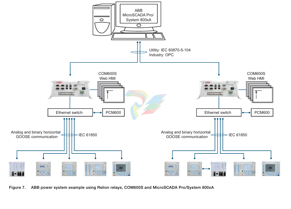
The numerical feeder protection relays of the 610 series support a wide range of standard communication protocols, among them the IEC 61850, IEC 60870-5-103, DNP3, Modbus, Profibus, LON and SPA communication protocols.
Protection functions
The protection relay offers overcurrent and thermal overload protection, earth-fault and phase-discontinuity protection for cable feeders, and three-pole, multi-shot autoreclose functions for overhead-line feeders.
Enhanced with optional hardware, the protection relay also features two light detection channels enabling arc fault protection of the switchgear, busbar system and cable terminals.
The numerical feeder protection relays of the 610 series support a wide range of standard communication protocols, among them the IEC 61850, IEC 60870-5-103, Modbus, Profibus and DNP3 communication protocols.
The connection of the CTs to REF610 depends on the available number and types of CTs in the feeder cubicle. Generally an outgoing feeder is equipped with three phase current transformers for high- and low-set overcurrent protection. The residual current for the earth-fault protection can be derived from the three phase currents. It can also be measured with a ring-type cable current transformer, should the outgoing feeder be a cable line and a sensitive earth-fault protection be required. Should the feeder cubicle be equipped with two phase current transformers, REF610 can still be used for high- and low-set overcurrent protection including phase discontinuity and phase unbalance protection.
Measurement
The protection relay continuously measures the phase currents and the residual current. Further the protection relay calculates the thermal overload of the protected object, the phase unbalance value, the one-minute demand value, the demand value for a specified time frame and the maximum one-minute demand value over a specified time frame.
The values measured can be accessed locally via the user interface on the protection relay's front panel or remotely via the serial communication interface of the protection relay.
Disturbance recorder
The protection relay is provided with a built-in battery backed up digital disturbance recorder for four analog signal channels and eight digital signal channels. The analog channels can be set to record the curve form of the currents measured. The digital channels can be set to record external or internal relay signals, for example the start or trip signals of protection relay's stages, external blocking or control signals. Any digital relay signal such as a protection start or trip signal, or an external relay control signal can be set to trigger the recording. The recordings are stored in a nonvolatile memory from which the data can be uploaded for subsequent fault analysis.
Event recorder
To provide network control and monitoring systems with feeder level event logs, the protection relay incorporates a nonvolatile memory with capacity of storing 100 event codes including the time stamps.The nonvolatile memory retains its data also in case the protection relay temporarily loses its auxiliarysupply.The event log facilitates detailed pre- and post-fault analyses of feeder faults and distribution disturbances.
Circuit-breaker monitoring
The protection relay constantly monitors the tear and wear of the protected feeder's circuit breaker by using a set of built-in condition monitoring counters. The monitoring counters provide the circuit breaker with operational history data. This data can be used for scheduling preventive maintenance programs for the circuit breaker.
Trip-circuit supervision
The trip-circuit supervision continuously monitors the availability and operability of the trip circuit. It provides open circuit monitoring both when the circuit breaker is in its closed and in its open position. It also detects loss of circuit-breaker control voltage.
Self-supervision
The relay’s built-in self-supervision system continuously monitors the state of the relay hardware and the operation of the relay software. Any fault or malfunction detected is used for alerting the operator.
A permanent relay fault blocks the protection functions to prevent incorrect operation.
Inputs/Outputs
• Four current transformers
• Two digital inputs
• Three additional digital inputs on an optional I/0 module
• Three normally open heavy duty output contacts
• Two change-over signal output contacts
• Three additional signaling contacts on an optional I/O module
• One dedicated IRF contact
• Input/output contacts freely configurable
Communication
The protection relays are connected to the fiber-optic communication bus directly or via bus connection modules and gateways. The bus connection module converts the protection relay's electrical signals to optical signals for the communication bus and, vice versa, the communication bus' optical signals to electrical signals for the protection relay.

Mounting methods
Using the appropriate mounting accessories, the standard relay case for the 610 series relays can be flush mounted, semi-flush mounted or wall mounted. The flush mounted and wall mounted relay cases can also be mounted in a tilted position (25°) by using special accessories.
Further, the relays can be mounted in any standard 19” instrument cabinet by means of 19” mounting panels available with cut-outs for one or two relays.Alternatively, the relays can be mounted in 19” instrument cabinets by means of 4U Combiflex equipment frames.
For routine testing purposes, the relay cases can be equipped with test switches, type RTXP 18, which can be mounted side by side with the relay cases.
Mounting methods
• Flush mounting
• Semi-flush mounting
• Semi-flush mounting in a 25° angle
• Rack mounting • Wall mounting
• Mounting to a 19" equipment frame
• Mounting with an RTXP 18 test switch to a 19" rack
Relay case and plug-in unit
As a safety measure, the relay cases for the current measuring protection relays are provided with automatically acting contacts for short-circuiting the CT secondaries, when a relay plug-in unit is withdrawn from the relay case. In addition, the relay case is provided with a mechanical coding system to prevent the current measuring relay plug-in units from being inserted into a case for a voltage protection relay unit and vice versa, that is the relay cases are associated to a certain type of relay plug-in unit.
There is, however, a universal relay case available, which is not associated to a certain plug-in unit type. When a relay plug-in unit is plugged into such a relay case for the first time, the relay case automatically adapts to that particular protection relay type, that is the short-circuiting contacts are activated as well as the mechanical blocking system. Hereafter, the relay case is permanently associated to a certain protection relay type.
Selection and ordering data
When ordering protection relays and/or accessories, please specify the following information: order number, HMI language set number and quantity. The order number identifies the protection relay type and hardware and is labelled on the marking strip under the lower handle of the protection relay.
Use the ordering key information in F i g u r e 7 to generate the order number when ordering complete protection relays.
Approvals
REF610 has been granted a preliminary EDF approval:
Number EDF R&D H-M2A-2006-02557-FR.
Certificates
KEMA has issued a Type test Certificate of Complete type test for the 610 series products. Certificate No. 08-1071, 08-1072 and 08-1073.
DNV (Det Norske Veritas) has issued a Type Approval Certificate for the 610 series protection relays. Certificate No. E-9945. The 610 series protection relays comply with Det Norske Veritas' Rules for Classification of Ships, High Speed & Light Craft and Det Norske Veritas' Offshore Standards.
The ENA (Energy Networks Association) Protection Assessment Panel has issued a Notice of Conformity Certificate to REF610. Notice of Conformity No. 154 Issue: 1, General & Environmental Self Certification Statement No. SC001 Issue B, Functional Assessment Statement(s) No. FA001-05 Issue 1.
Korea Electrical Safety Corporation (KESCO) has issued a KAS V-Check Mark certificate for the 610 series products. Ref. Cert. No. KAS-KESCO-7018-02.
References
The latest relevant information on the REF610 protection relay is found on the product page. Scroll down the page to find and download the related documentation.
-
ADLINK cPCI-R6200 high-performance 6U CompactPCI Rear Transition Module (RTM)
-
Adlink cPCI-7248 48-CH Opto-22 Compatible Digital I/O Module
-
ADLINK DLAP-211-JNX/DLAP-211-JT2/ DLAP-211-Nan
-
ADLINK cPCI-3544 4-Port RS-422/485 Isolated Serial Communications Card
-
Hirschmann MSP30-16040SCZ999HHE2A Manage the basic unit of the industrial DIN-Rail switch
-
Hirschmann MSP30-16040SCY999HHE2A
-
Hirschmann RS20-0400S2S2SDAEHC09.0.00 Management-type industrial fast Ethernet switch
-
Hirschmann Belden OCTOPUS OS20-002800T5T5T5-TBBY999GMSE3S Manageable industrial Ethernet switch
-
HIRSCHMANN OS20-000800T5T5T5-TBBU999H5SE2S
-
HIRSCHMANN RS20-0800M4M4SDAEHC09.0.14 industrial switch
-
Hirschmann RS20-0800T1T1SDAUHC RS20-0800T1T1SDAE
-
Hirschmann MSM20-M2M2M2M2SY9HH9E99.9 Fast Ethernet Media Module
-
HIRSCHMANN MAR1040-4C4C4C4C9999SMMHPHH Managed Etherne
-
HIRSCHMANN MAR1040-4C4C4C4C9999SMMHPHH Managed Etherne
-
HIRSCHMANN MAR1040-4C4C4C4C9999SM9HRHH Managed Etherne
-
HIRSCHMANN MAR1040-4C4C4C4C9999SM9HPHH05.1.00 industrial switch
-
HIRSCHMANN MM20-P9P9M2T1SAHH Fast Ethernet media module
-
HIRSCHMANN MM20-P9T1T1T1SAHH hot-swappable hybrid media module
-
HIRSCHMANN MM20-Z6Z6T1M2SAHH Fast Ethernet media module
-
HIRSCHMANN MM20-Z6M2M2T1SAHH Fast Ethernet media module
-
HIRSCHMANN MM20-Z6Z6Z6T1SAHH media module.
-
HIRSCHMANN MM20-Z6T1T1T1EBH Fast Ethernet media card.
-
Hirschmann MM20-Z6T1T1T1SAHH Hot-swappable fast Ethernet media module
-
Hirschmann MM20-Z6Z6M2M2EBH media module
-
HIRSCHMANN MM20-Z6Z6T1T1SZHH Technical Datasheet & SEO Guide
-
HIRSCHMANN MM20-Z6Z6T1T1EBH Technical Datasheet & Overview
-
HIRSCHMANN MM20-Z6Z6Z6Z6SZHH Media Module
-
HIRSCHMANN MM20-M4M2M2T1SAHH Media Module
-
HIRSCHMANN MM20-M4T1M2T1SAHH Media Module
-
HIRSCHMANN MM20-M2M2T1T1EBH Media Module
-
HIRSCHMANN MM20-M2M2T1T1SAHH Media Module
-
HIRSCHMANN MM20-M2T1T1T1TAHH Media Module
-
HIRSCHMANN MM20-M2T1T1T1EBH Media Module
-
HIRSCHMANN MM20-M2T1T1T1SAHH Media Module
-
HIRSCHMANN MM20-M2T1T1T1SAHH Media Module
-
HIRSCHMANN MM20-M2T1T1T1SAHH Media Module
-
HIRSCHMANN MM20-M2T1T1T1SAHH Media Module
-
HIRSCHMANN MM20-M2M2M2M2EBH Industrial Ethernet Media Module
-
HIRSCHMANN RS20-1600S2S2SDAEHH09.0.14 Ethernet switch
-
HIRSCHMANN MSM20-M2M2T1T1SY9HH9E99.9.99
-
HIRSCHMANN MSM20-M2M2M2M2SY9HH9E Ethernet media modul
-
HIRSCHMANN SPIDER-PL-20-05T1999999TWVHHHH Industrial Ethernet Rail Switch
-
Hirschmann SPIDER-PL-20-07T1M2M299TWVHHHH Industrial ETHERNET Rail Switch
-
Hirschmann (Belden) RS20-1600M2M2SDAEHC09.1.00 DIN-rail managed industrial Fast Ethernet switch
-
Hirschmann (Belden) RS30-1602O6O6TDAPHC09.1.00 DIN-rail managed industrial Ethernet switch
-
Hirschmann RS30-2402O6O6SDAP Ethernet switch
-
Hirschmann (Belden) RS30-2402O6T1SDAPHH09.0.13 DIN-rail industrial Ethernet switch
-
Hirschmann (Belden) RS30-2402O6T1SDAPHH09.0.13 DIN-rail industrial Ethernet switch
-
Hirschmann (Belden) SPIDER-PL-20-04T1S29999TY9HHHH Ethernet DIN-rail switch
-
HIRSCHMANN RS20-1600T1T1SDAUHX Switch
-
HIRSCHMANN BRS42-0012OOOO-SPCZ99HHSES industrial switch
-
Hirschmann RS20-0800S2S2TDHPHH09.0.14 Fast Ethernet DIN rail switch.
-
HIRSCHMANN MM20-Z6Z6M2M2SAHH Hybrid Fast Ethernet Media Module
-
HIRSCHMANN MM20-Z6Z6T1T1SAHH hot-swappable hybrid Fast Ethernet Media Module
-
HIRSCHMANN MM20-P9P9T1T1SAHH Hybrid Fast Ethernet Media Module
-
HIRSCHMANN MM20-M4T1T1T1SAHH Hybrid Fast Ethernet Media Module
-
HIRSCHMANN MM20-M4M4T1T1SAHH Hybrid Fast Ethernet Media Module
-
HIRSCHMANN MM20-M2M2M2M2SZHH Ethernet media module
-
HIRSCHMANN MM20-M2M2M2M2SAHH Ethernet media module
-
HIRSCHMANN MM20-T1T1T1T1EBH 4-port Fast Ethernet Copper Cable Media Module
-
HIRSCHMANN MM20-T1T1T1T1SAHH 4-port Fast Ethernet Copper Cable Media Module
-
HIRSCHMANN MM20-Z6Z6EBH Hot-swappable fast Ethernet media module
-
HIRSCHMANN MM20-Z6Z6SAHH Ethernet media module
-
HIRSCHMANN MM20-Z6Z6Z6Z6EBH Industrial Media Module
-
MSM40-T1T1T1TZ9HH9E99.9.99 HIRSCHMANN Switch
-
HIRSCHMANN MS20-0800SAAEHC / MS20-0800SAAEHC0 8-port modular Layer 2 management Ethernet switch
-
Hirschmann RSPM20-4T14T1SZ9HHS9 Switch RSPM20-4T14T1SZ9HHS9
-
HIRSCHMANN RS20-1600M2M2SDAEHH09.1. RS20/30/40 Managed Switch configurator
-
HIRSCHMANN RS20-1600M2M2SDAEHX09.0.00 Ethernet switch
-
HIRSCHMANN BELDEN SPIDER-PL-20-07T1M2M299TY9HHHH / SPIDERPL2007T1M2M299TY9HHHH
-
HIRSCHMANN MM3-1FXS2/3TX1 Switching Board Module
-
HIRSCHMANN RSPE30-24044O7T99-SCCV999HHSI2SXX.X.XX Switch
-
HIRSCHMANN RSPE30-24044O7T99-ECCP999HHSE2A08.1.00 Industrial-grade fanless management-type Ethernet switch
-
HIRSCHMANN RS30-1602OOZZSDAEHC09.1.00 DIN-rail-mounted managed Layer 2 Ethernet switch
-
HIRSCHMANN MACH104-20TX-F Managed 24-port Full Gigabit 19" Switch
-
HIRSCHMANN Switch RS20-0800M4M4SDAE
-
Hirschmann RS30-1602O6O6SDAEHH09.1. Management-type Ethernet switch
-
Hirschmann RS30-1602OOZZSDAEHC09.0.10 Open rack-style Ethernet switch
-
HIRSCHMANN RSPE30-24044O7T99-SCCV999HHSI2SXX.X.XX High-Availability Seamless Redundancy
-
HIRSCHMANN RSPE30-24044O7T99-SCCZ999HHSE2A DIN-rail Ethernet switch
-
HIRSCHMANN MM2-4TX1-EEC switch
-
HIRSCHMANN MSM40-T1T1T1T1TZ9HH9E99.9.99 Module
-
HIRSCHMANN RS20 Rail Switch RS20-0400S4T1SDAEHC07.1.01
-
HIRSCHMANN M4-FAST8-SFP Fast Ethernet media module
-
HIRSCHMANN RS20-0400M2T1SDAP Managed Fast-Ethernet-Switch
-
HIRSCHMANN BELDEN SPIDER II 8TX/1FX EEC Industrial Ethernet Rail Switch
-
HIRSCHMANN MM3-2FXS2/2TX1
-
HIRSCHMANN RS2-4TX/1FX EEC Industrial Ethernet Rail Switch 2
-
RS30-0802O6O6SDAEHC09.0.10 HIRSCHMANN Switch
-
HIRSCHMANN m4-8TP-RJ45 Ethernet Media Module
-
HIRSCHMANN MSP30-24040SCZ9URHHE3A switch
-
Hirschmann rack MS30-1602SAAPHC
-
HIRSCHMANN RS2-FX/FX Industrial Switch Module
-
Rs1txfx - Hirschmann - Rs1-Tx/Fx Rail Switch
-
RS20-0800S2S2SDAEHC09.1.00 HIRSCHMANN Commutator
-
Hirschmann EAGLE20 TX/TX Industrial Security Router
-
Hirschmann SPIDER-SL-20-04T1S29999SY9HHHH Industrial Switch
-
HIRSCHMANN MAR1040-4C4C4C4C9999SMMHRHHXX.X. Gigabit Ethernet Switch configurator
-
Hirschmann MAR1040 Industrial Switch
-
HIRSCHMANN BELDEN RS30-1602O6O6SDAE
-
Hirschmann RS20-1600M2M2SDAUHC Ethernet DIN rail switch
-
HIRSCHMANN OCTOPUS24M industrial switch
-
HIRSCHMANN RS20-1600T1T1SDAE Management-type Ethernet switch
-
HIRSCHMANN RS20-1600T1T1SDAUHH industrial switch
-
HIRSCHMANN RS20-0800M2M2SDAPHC09.0.04 switch
-
Hirschmann MR 8-03 24V DC Industrial Modular Bridge/Router
-
HIRSCHMANN RS20-0400M2T1SDAPHC08.0.01 Managed Switch
-
MACH1130 Hirschmann Industrial Switch
-
HIRSCHMANN 943824-002 SPIDER 5TX Industrial Ethernet Switch
-
HIRSCHMANN RS30-0802O6O6SDAEHC09.1.00 Managed Industrial Switch
-
HIRSCHMANN RS20-0400M2M2TDAEHC04.0.01 Industrial Switch
-
HIRSCHMANN BRS20-0600Z6Z6-STCZ99HHSES Industrial Switch
-
HIRSCHMANN MACH104-20TX-FR-L3P Industrial Ethernet Switch
-
HIRSCHMANN RS40-0009CCCCEDBPHH06.0.01 Industrial Switch
-
HIRSCHMANN RS2-3TX/2FX EEC Industrial Ethernet Switch
-
Hirschmann MACH 1020/1030 Fast/Gigabit Rack Mount Switches
-
HIRSCHMANN RS20-0800M2M2SDAPHC09.0.14 Industrial Switch
-
HIRSCHMANN RS20-1600T1T1SDAEHC09.0.04 Industrial Switch
-
HIRSCHMANN RSB20-0800T1T1EAABHH Industrial Switch
-
HIRSCHMANN MACH4002-48+4G-L3E Industrial Backbone Switch
-
HIRSCHMANN RS20-0400S2T1SDAE Industrial Managed Switch
-
HIRSCHMANN RS20-0800S2T1SDAUHC Industrial Switch
-
HIRSCHMANN RS20-2400S4S4SDAEHC09.0.14 industrial switch
-
HIRSCHMANN OS20-001200T5T5T5- TBBZ999HHNE3S 08.1.00 industrial switch
-
HIRSCHMANN RS40-0009CCCCSDAEHH09.0.14 switch
-
Hirschmann RS20-1600T1T1SDAUHC Management-type Ethernet Switch
-
Hirschmann M1-8SFP Switche
-
Hirschmann Industrial Ethernet Ruggedized Switch MACH1000 Family
Add: High-tech Software Park, Xiamen City, Fujian Province
Mobile: +86-17750019513(WhatsApp)
Email: yy4291644@gmail.com
Website: https://www.abb-sis.com
.jpg)
.jpg)
.jpg)
.jpg)
.jpg)
.jpg)

-
ADLINK cPCI-R6200 high-performance 6U CompactPCI Rear Transition Module (RTM)
-
Adlink cPCI-7248 48-CH Opto-22 Compatible Digital I/O Module
-
ADLINK DLAP-211-JNX/DLAP-211-JT2/ DLAP-211-Nan
-
ADLINK cPCI-3544 4-Port RS-422/485 Isolated Serial Communications Card
-
Hirschmann MSP30-16040SCZ999HHE2A Manage the basic unit of the industrial DIN-Rail switch
