

T 6495-2 EN TROVIS 6495 Industrial Controller SAMSON
Outputs
− 3 analog outputs (AO1 to AO3) The signal type is set depending on the configuration.
− 0/4 to 20 mA − 0/2 to 10 V The outputs AO1 to AO3 can optionally be used for other signals as well. 7 digital outputs (4 relay outputs and 3 transistor outputs) The relay outputs can be used as follows:
− SO1 and SO2 as on/off or three-step output
− DO1 to DO4 as limit output
− DO5 and DO6 (transistor output) for status messages
− DO7 (transistor output) for fault alarms 4 relay outputs for two on/off or three-step outputs or four limit alarms 2 transistor outputs for status messages
− 1 transistor output for fault alarms
− 1 supply output The supply output can be used to supply a voltage for up to 4 two-wire transmitters and 4 digital inputs (21 V DC, max. 90 mA). Infrared interface Data are transmitted between the controller and the TROVIS VIEW software over an infrared interface, by default integrated into the controller and an infrared adapter (order no. 8864-0900) connected to a computer (see the Mounting and Operating Instructions EB 6495-2). Communication interface Optionally, the controller can be equipped with one of the fol lowing interface boards. The boards can also be retrofitted.
− RS-232/USB interface board
− One RS-232 interface with RJ-12 jack
− One USB interface with 5-pin mini-B port The RS-232 data transfer uses an SSP or Modbus RTU protocol. The memory pen-64 can be used with controllers fitted with an RS-232/USB interface board to load data configured in TROVIS-VIEW or transferred from another controller.
− RS-485/USB interface board − RS-485 interface (4 terminals) and
− USB interface (5-pin mini-B port)
Operation
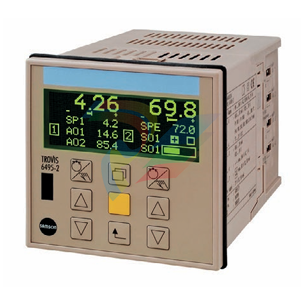
Display and operating controls
The device has nine operating keys, of which three are as signed to each controller channel. Depending on the selected control type, one or two controllers are activated. The read ings and controls of the controller [1] are located on the left half of the device and on the right half for controller [2] (or optionally vice versa). The row of keys in the middle is used for both controllers.
Operating leve
After the supply voltage has been switched on, the controller is in operating level. The readings of the controlled variable, the reference variable and the manipulated variable for each controller as well as a bar graph for error are indicated on the display (1). Depend ing on the configuration, status alarms of the digital inputs and outputs can be shown. The operating menu allows set points to be switched and control parameters to be changed. The two rows at the bottom of the display can be assigned as desired. Numerous signals and interim outputs relating to the internal controllers can be selected. For example, the values or a bar graph of two outputs in split-range operation can be displayed.
Configuration and parameterization
The controller is adapted to the selected application in the configuration level. The configuration items are arranged in hierarchical menus. All settings are displayed as plain text.
-
Schneider GUTOR OC0935 Power Factor Sampling Board
-
Schneider GUTOR OC0922 Analog Signal Isolation Board
-
Schneider GUTOR OC0908 Battery Voltage Detection Board
-
Schneider GUTOR OC0947 Temperature / IGBT Sampling Board
-
Schneider GUTOR OP2601 Communication Expansion Board
-
Schneider Electric GUTOR OP2312 bypass control board
-
Schneider Electric GUTOR OP2130 Cooling Fan Monitoring & Control Board
-
Schneider Electric GUTOR OP2010 Battery Test Board / Battery Management Diagnostic Card
-
Schneider Electric GUTOR OP2552 Three-phase Power Connection Board Assembly
-
Schneider Electric GUTOR OP1922A Parallel Control Board / Load-Sharing Synchronization Module
-
Schneider Electric GUTOR OP6290B Inverter Feedback Acquisition Board / Signal Scaling Module
-
Schneider GUTOR OP6280 Basic Signal Board
-
Schneider Electric GUTOR OP2456 / OP2456B Main control board
-
Schneider Electric GUTOR OP2452 Power Plug-in Panel
-
Schneider Electric GUTOR OP2450 Parallel Communication Board
-
Schneider Electric GUTOR OP2406 Interface Fuse Monitoring Board
-
Schneider Electric GUTOR OC0919 High-Power Semiconductor Module
-
Schneider Electric GUTOR OP6281A System Logic Interface Board
-
Schneider Electric GUTOR OP6285A Power Signal Acquisition Board
-
Schneider Electric GUTOR OP2438 Fan Monitor & Drive Protection Board
-
Schneider Electric GUTOR OP2446 Main Control CPU Board
-
ROLLS-ROYCE CE05-00 Steering Gear Control Module
-
ROLLS-ROYCE MARINE AS-BRATTVAAG WRC1021A CONTROLLER CARD
-
ROLLS ROYCE DECK MACHINERY MPC-300-A7029099 TERMINAL CONTROLLER UNIT
-
ROLLS-ROYCE HELICON THRUSTER CONTROL PANEL LF90S-01-06
-
Rolls-Royce PCC1030C Panel Controller Card
-
Rolls-Royce RRDIO15 Remote Digital Input/Output Module
-
Rolls-Royce TDI-11 Pitch & Direction Indicator Module
-
Rolls-Royce CCN 01 CANman Controller Network Module
-
Rolls-Royce SLIO 01 CANman Controller Network Module
-
Rolls-Royce MPC-210 Winch & Propulsion Control Module
-
Rolls-Royce MTI-144 Engine Control Module
-
Rolls-Royce Tenfjord FB10-002 Steering Gear Module (E-4500-40-1)
-
ROLLS ROYCE MARINE AS CIRCUIT BOARD (PCB) RRAI016
-
Rolls-Royce Marine AS PIP6-1 Marine Controller
-
ROLLS-ROYCE MPC-300 STARTER CONTROL UNIT A7029099
-
Rolls-Royce Data Respons MPCF1-10.4" Maritime Panel Computer
-
ROLLS-ROYCE MARINE OLC-40009 PCB CARD
-
Rolls-Royce Marine Brattvaag WRC1021B Controller Board
-
ROLLS-ROYCE CCN 01 & ROLLS-ROYCE SLIO 02 CANMAN CONTROLLER NETWORK
-
ROLLS-ROYCE ATC-3-A7033172 AQUAMASTER TURNING CONTROLLER
-
ROLLS-ROYCE POSCON V.3 JOYSTICK MODULE 6459
-
Rolls-Royce Marine 389-496-00 Joystick Remote Control Panel 6799-W, 389-996-00
-
Rolls-Royce data respons 10.4'' Panel Computer 98H010A0000I/R10I53S
-
Rolls-Royce H1127.0101 Marine Controller 000068308
-
Rolls-Royce CU40-0106-50 Steering Gear Control Panel
-
Beckhoff Polaris CP7011-1002-0010 operator operator HMI display 30.5 cm
-
Beckhoff AM8052-0JH1-0000 Servomotor 10.7 Nm (M0), F5 (104 mm)
-
Beckhoff AM8052-0JH1-0000 Servomotor 10.7 Nm (M0), F5 (104 mm)
-
Beckhoff BX5100-0000 CANopen Bus Terminal Controller
-
Beckhoff CX9020-0115 PLC Module CX90200115
-
Beckhoff module EJ7211-0010 EtherCAT plug-in module
-
BECKHOFF AX5203-0000 Servo Driver
-
BECKHOFF CP6201-0001-0020 24VDC UNMP
-
Beckhoff CX5120-0135 Embedded PC CPU Module
-
BECKHOFF C5240-0020/000224115 Plc Module
-
Beckhoff CP2918-0000 PanelCP29xx-0000 | Multi-touch built-in Control Panel with DVI/USB Extended interface
-
Beckhoff CX2020-0122 Embedded PC Controller
-
Beckhoff C6640-0040 Control Cabinet Industrial PC 7-Slot
-
BECKHOFF CONTROL CABINET INDUSTRIAL PC - C6930-1062-0050
-
Beckhoff Automation EtherCAT Terminal EK1100 EK1122
-
Beckhoff CP6533-0001-0060 IPC
-
Beckhoff EK9500 | EtherNet/IP™ Bus Coupler
-
Beckhoff CP6202-1047-0050 - An industrial-grade embedded panel computer.
-
Beckhoff C6650-0040 Industrial PC
-
BECKHOFF CX5230-0185 / 000119805 PLC Module
-
Beckhoff EL3773 PLC Module
-
BECKHOFF EL4732 (PKG OF 10) NSMP
-
Beckhoff CP6202-0001-0010 Economy Built-In Panel
-
Beckhoff AX5206-0000-0202 Digital Compact Servo Drives 2-channel
-
Beckhoff Panel PC CP6606-0001-0020 7-inch Economy Panel PC
-
Beckhoff CPU basic module CX2020-0155 + power supply module CX2100-0004
-
Beckhoff CP2913-000 Multi-Touch Display
-
Beckhoff CP6500-1012-0060 14250369 Control Cabinet
-
Beckhoff CP7902-0001-0000 Economy Control Panel with DVI/USB Extended interface
-
Beckhoff C6920-0010 Core Duo 2.00 GHz
-
BECKHOFF C3640-0050 Build-in Industrial PCs
-
Beckhoff KL6023-0000 KL6023 EnOcean Wireless-Adapter
-
Kollmorgen AKM54G-ANC2DB00 servo motor
-
Kollmorgen S200 Series S20350-VTS SERVO DRIVE
-
KOLLMORGEN AKD-P00606-NBCC-I000 SERVO DRIVE
-
Kollmorgen MV65WKS-CE310/22PB Servo Drive Control Module
-
Kollmorgen S20360-VTS-021 Servo Drive
-
KOLLMORGEN CR06550 High-precision digital servo amplifier
-
KOLLMORGEN DBL5N01050-03S-VV0-S40 Phase AC Synchronous Brushless Servo Motor
-
KOLLMORGEN S70301-NANANA-024 SERVO DRIVE
-
Kollmorgen S20360-VTS S200 Series Servo Drive
-
Kollmorgen RBE-03011-A00 Brushless Frameless Servo Motor
-
KOLLMORGEN AKD-T00306-NBAN-0000 INPUT SERVO DRIVE
-
KOLLMORGEN S700 Servo Controller S70302-NANANA
-
Kollmorgen AKD-P00607-NBEC-0000 400/480VAC 4.40KVA Servo Drive.
-
KOLLMORGEN S70102-NANANA SERVO DRIVE
-
KOLLMORGEN AKM21E-ANSNEH02 PM Servo Motor & PRD-AMPE25EB-00 Servo Drive Array
-
KollMorgen SC1R06260 Servo Drive 1.4/2.2 KVA 115230 Vac
-
Kollmorgen AKD-P00306-NBAN-0000 Servo Drive
-
Kollmorgen TTB2-2042-3052-A DC Motor Industrial Drive 5.5A 185 oz/inIntegrated safety
-
KOLLMORGEN SERVOSTAR 610-AS SERVO AMPLIFIER_SERVOSTAR610AS_S61001
-
KOLLMORGEN Seidel 60WKS-CE240/26PB 26A Servo Drive Module Control 60WKS-M240/26
-
KOLLMORGEN PRD-0016400P-10 & PRD-0016600D-30 Axis Control System Modules
-
KOLLMORGEN Seidel DBL5N01700-03S-000-S40 Servo Motor
-
HIRSCHMANN RS30-0802O6O6SDAP RAIL SWITCH
-
Hirschmann RS20-1600M2T1SDAEHH03.1.02 Rail Switch
-
Hirschmann RSPM20-4T14T1EV9HHS999.9.99 Managed Ethernet Switch
-
Hirschmann BELDEN RS40-0009CCCCSDAPHH09.0.14 / RS400009CCCCSDAPHH09014
-
Hirschmann RS40 Rail Switch RS40-0009CCCCSDAE
-
Hirschmann BELDEN RS30-0802T1T1SDAP / RS300802T1T1SDAP Fully Managed Layer 2 Compact Rail Switch
-
Hirschmann BELDEN RS20-0800M2M2SDAUHH / RS200800M2M2SDAUHH
-
Hirschmann EAGLE30-04022O6TT999SCCY9HSE3F Industrial Firewall Router Switch
-
Hirschmann RS20-1600T1T1SDAEHH09.0.14 RS20 Rail Mount Ethernet Switch
-
Hirschmann EAGLE 0200T1T1TDDY90000HHE05.3.03 Industrial Security Router
-
Hirschmann - BELDEN MIPP-AD-1L9P
-
HIRSCHMANN RSPM20-4Z64Z6TV9HHS9 942 106-999 RAIL SAFETY SWITCH
-
HIRSCHMANN FIBEROPTIC MODULE FIP P/N: OZDFIPG3 T
-
HIRSCHMANN RS20-1600M2M2SDAUHH Ethernet rack-mounted switch
-
BELDEN RS20-0400T1T1SDAEHH04.0.01 / RS200400T1T1SDAEHH04001
-
HIRSCHMANN MM2-4FXM3 MICE Media Module
-
Hirschmann RS20-2400T1T1SDAP / RS20-2400T1T1SDAPHH05.0.02
-
GE MLJ1005B010H00C MLJ Digital Synchromism Check
-
ALSTOM MICROTECH DX21-M2 Digital Excitation Controller
-
HIRSCHMANN BRS20-1200ZZZZ-STCY99HHSES
-
HIRSCHMANN MM3-4FXM2 MICE Media Module
-
Hirschmann RSB20-0800T1T1SAABHH 8Port ENet Rail Switch RSB20
-
Hirschmann MACH102-8TP Ethernet Switch
-
SAACKE DDZ-M marine steam pressure atomizer
-
SAACKE SKV-A marine rotary cup atomizer
-
SAACKE Seavis HMI05e
-
Kollmorgen MMC-SD-2.0-230 Servo Drive 100-240VAC 2KW 10A Output 3PH 100-240VAC
-
Kollmorgen Servo drive CR10550
Add: High-tech Software Park, Xiamen City, Fujian Province
Mobile: +86-17750019513(WhatsApp)
Email: yy4291644@gmail.com
Website: https://www.abb-sis.com
.jpg)
.jpg)
.jpg)
.jpg)
.jpg)
.jpg)

-
Schneider GUTOR OC0935 Power Factor Sampling Board
-
Schneider GUTOR OC0922 Analog Signal Isolation Board
-
Schneider GUTOR OC0908 Battery Voltage Detection Board
-
Schneider GUTOR OC0947 Temperature / IGBT Sampling Board
-
Schneider GUTOR OP2601 Communication Expansion Board
