

Triconex 3351S2 Controller Features
To ensure the highest possible system integrity at all times, the Trident controller includes the following features:
• Provides Triple Modular Redundant (TMR) architecture, whereby each of three identical channels independently executes the application, and specialized hardware and software mechanisms vote all inputs and outputs.
• Withstands harsh industrial environments.
• Integrates the I⁄O module with the termination assembly.
• Enables field installation and repair to be done at the module level while the controller remains online without disturbing field wiring.
• Supports up to 14 I⁄O modules. (If the controller includes AO or PI Modules, up to 10 modules are supported.)
• Provides TriStation and Modbus communication directly from the Main Processor (MP) or from the Communication Module (CM).
• Executes applications developed and debugged using TriStation.
• Provides a dedicated co-processor which controls the input and output modules to reduce the workload of the MP. Each I⁄O module is supported by custom application-specific integrated circuits (ASICs), which scan inputs and perform diagnostics to detect hardware faults. Output module ASICs do the following:– Supply information for voting of output data.– Check I⁄O loop-back data from the output terminal for final validation of the output state.– Perform diagnostics to detect hardware and field-wiring problems.
• Provides integral online diagnostics with adaptive-repair capabilities.
• Allows normal maintenance while the controller is operating, without disturbing the controlled process.
• Supports hot-spare I⁄O modules for critical applications for which prompt service may not be possible.
• Provides integral support for redundant field and logic power sources.
Fault Tolerance
Fault tolerance, the most important capability of the controller, is the ability to detect transient and steady-state error conditions and take appropriate corrective action online. Fault tolerance provides an increase in safety and the availability of the controller and the process being controlled. The Trident controller provides fault tolerance through TMR architecture.
The controller consists of three identical channels (except for the power modules which are dual-redundant). Each channel independently executes an application in parallel with the other two channels. Voting mechanisms qualify and verify all digital inputs and outputs from the field; analog inputs are subject to a mid-value selection process.
Because each channel is isolated from the others, no single-point failure in any channel can pass to another. If a hardware failure occurs in one channel, the faulty channel is overridden by the other channels. Repair consists of removing and replacing the failed module in the faulty channel while the controller is online and without process interruption.
Extensive diagnostics on each channel, module, and functional circuit immediately detect and report operational faults by means of indicators or alarms. All diagnostic fault information is accessible by the application and the operator. The operator can use the diagnostic information to modify control actions or direct maintenance procedures.
Controller Architecture
The controller features TMR architecture to ensure fault tolerance and error-free, uninterrupted control in the event of hard failures of components or transient faults from internal or external sources.
Each I⁄O module houses the circuitry for three independent channels. Each channel on the input modules reads the process data and passes that information to its respective MP. The three MPs communicate with each other using a proprietary, high-speed bus called the TriBus.
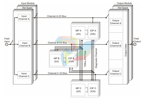
Once per scan, the MPs synchronize and communicate with their neighbors over the TriBus. The TriBus forwards copies of all analog and digital input data to each MP and compares output data from each MP. The MPs vote the input data, execute the application, and send outputs generated by the application to the output modules. In addition, the controller votes the output data on the output modules as close to the field as possible to detect and compensate for any errors that could occur between the TriBus voting and the final output driven to the field.
For each I⁄O module, the controller can support an optional hot-spare module. If present, the hot-spare takes control if a fault is detected on the primary module during operation. The hot-spare position is also used for the online hot repair of a faulty I⁄O module.
Main Processor Architecture
A controller contains three MPs. Each MP controls a separate channel and operates in parallel with the other two MPs. A dedicated I⁄O control processor on each MP manages the data exchanged between the MP and the I⁄O modules. A triplicated I⁄O bus, located on the baseplates, extends from one column of I⁄O modules to another column of I⁄O modules using I⁄O bus cables. As each input module is polled, the appropriate channel of the I⁄O bus transmits new input data to its MP. The input data is assembled into a table in the MP and is stored in memory for use in the voting process.
The individual input table in each MP is transferred to its neighboring MP over the TriBus. After this transfer, voting takes place. The TriBus uses a programmable device with direct memory access to synchronize, transmit, and compare data among the three MPs. If a disagreement occurs, the signal value found in two of three tables prevails, and the third table is corrected accordingly. One-time differences which result from sample timing variations are distinguished from a pattern of differing data. Each MP maintains data about necessary corrections in local memory. Any disparity is flagged and used at the end of the scan by the built-in fault analyzer routines to determine whether a fault exists on a particular module.
The MPs send corrected data to the application. The 32-bit MP executes the application in parallel with the neighboring MPs and generates a table of output values that are based on the table of input values according to user-defined rules.The I⁄O control processor on each MP manages the transmission of output data to the output modules by means of the I⁄O bus.
Using the table of output values, the I⁄O control processor generates smaller tables, each corresponding to an individual output module. Each small table is transmitted to the appropriate channel of the corresponding output module over the I⁄O bus. For example, MP A transmits the appropriate table to channel A of each output module over I⁄O bus A. The transmittal of output data has priority over the routine scanning of all I⁄O modules.
Each MP provides a 16-megabyte DRAM for the user-written application, sequence-of-events (SOE) and I⁄O data, diagnostics, and communication buffers. (For more information about SOE, see the Sequence of Events Recorder User's Manual.) The application is stored in flash EPROM and loaded in DRAM for execution. The MPs receive power from redundant 24 volts DC power sources. If an external power failure occurs, all critical retentive data is stored in NVRAM. A failure of one power source does not affect controller performance. If the controller loses power, the application and all critical data are retained indefinitely.
Bus and Power Distribution
The triplicated I⁄O bus, as shown on page 8, is carried baseplate-to-baseplate using Interconnect Assemblies, I⁄O Extender Modules, and I⁄O bus cables. The redundant logic power distribution system is carried using Interconnect Assemblies and I⁄O Extender modules.
serial links operating at 25 megabits per second. The TriBus synchronizes the MPs at the beginning of a scan. Then each MP sends its data to its upstream and downstream neighbors. The TriBus takes the following actions:
• Transfers input, diagnostic, and communication data
• Compares data and flags disagreements with the output of the previous scan and program memory
An important feature of the Trident controller architecture is the use of a single transmitter to send data to both the upstream and downstream MPs. This ensures that the same data is received by the upstream processor and the downstream processor.
Field signal distribution is local to each I⁄O baseplate. Each I⁄O module transfers signals to or from the field through its associated baseplate assembly. The two I⁄O module slots on the baseplate tie together as one logical slot. The right or left position holds the active I⁄O module and the other position holds the hot-spare I⁄O module. Each field connection on the baseplate extends to both active and hot-spare I⁄O modules. Consequently, both the active module and the hot-spare module receive the same information from the field termination wiring. A triplicated I⁄O bus transfers data at 2 megabits per second between the I⁄O modules and the MP. The I⁄O bus is carried baseplate-to-baseplate and can be extended to multiple columns of I⁄O modules. Each channel of the I⁄O bus runs between one MP and the corresponding channel on the I⁄O module. The I⁄O bus extends between DIN rails using a set of three I⁄O bus cables. Logic power for the modules on each DIN rail is distributed using two independent power rails. Each module along the DIN rail draws power from both power rails through redundant DC-DC power converters.
Each channel is powered independently from these redundant power sources.
Controller Communications
The controller can communicate directly to TriStation and other devices through the Main Processor Module and the Communication Module.
Main Processor Module
Each MP can provide direct TriStation and Modbus communication. Each MP provides:
• One Tristation (Ethernet) port for downloading an application to the controller and uploading diagnostic information.
• One Modbus RS-232/RS-485 serial port which acts as a slave while an external host computer is the master. Typically, a distributed control system (DCS) monitors—and optionally updates—the controller data directly though an MP.
Communication Module
The Communication Module (CM) provides an optional, three-to-one interface to
the MPs that supports various protocols for communication with external hosts. A
single controller supports up to two CMs on one CM Baseplate. Each CM operates
independently. Two CMs can provide redundant communication connections or
independent communication ports.
Each CM provides three RS-232/485 serial ports and two Ethernet ports. These ports support a variety of communication methods, protocols, and physical media types that enable the controller to communicate with:
• External host computers
• Distributed control systems (DCS)
• Open networks
• Network printers
• Other Trident or Tricon V9 controllers
Input/Output Modules
The controller manages the data exchanged between the MP and the following I⁄O modules:
• Analog Input Module
• Analog Output Module
• Digital Input Module
•Digital Output Module
• Pulse Input Module
• Solid-State Relay Output Module
Analog Input Module
places the results into a table of values. Each input table is passed to its associated MP using the corresponding I⁄O bus. The input table in each MP is transferred to its neighbors across the TriBus. The middle value is selected by each MP and the input table in each MP is corrected accordingly. In TMR mode, the mid-value data is used by the application; in duplex mode, the average is used. Each AI Module is guaranteed to remain in calibration for the life of the controller; periodic manual calibration is not required. Special self-test circuitry is provided to detect and alarm all stuck-at and accuracy fault conditions in less than 500 milliseconds, typically. This safety feature allows unrestricted operation under a variety of multiple-fault scenarios.
Analog Output Modules
AO Module receives three tables of output values, one for each channel from the corresponding Main Processor. Each point on each channel has its own digital-to analog converter (DAC). One of the three channels is selected to drive the analog outputs. The outputs of the selected channel are continuously verified by I⁄O loop back inputs from each point, which are read by all three channels. If a fault occurs in the driving channel, the channel is declared faulty, is disabled, and a new channel is selected to drive the field device. The selection of the driving channel alternates among the channels so that all three channels are periodically tested. Each AO Module is guaranteed to remain in calibration for the life of the controller; periodic manual calibration is not required.
Digital Input Module
A Digital Input Module contains the circuitry for three identical channels (A, B, and C). Although the channels reside on the same module, they are completely isolated from each other and operate independently. Each channel conditions signals independently and provides optical isolation between the field and the controller. A fault on one channel cannot pass to another. In addition, each channel contains a proprietary ASIC which handles communication with its corresponding MP, and supports run-time diagnostics. Each of the three input channels measures the input signals from each point on the baseplate asynchronously, determines the respective states of the input signals, and places the values into input tables A, B, and C, respectively. Each input table is interrogated at regular intervals over the I⁄O bus by the I⁄O communication processor located on the corresponding MP. For example, MP A interrogates Input Table A over I⁄O Bus A. Special self-test circuitry is provided to detect and alarm all stuck-at and accuracy fault conditions in less than 500 milliseconds, typically. This safety feature allows unrestricted operation under a variety of multiple-fault scenarios. The input diagnostics are specifically designed to monitor devices which hold points in one state for long periods of time. The diagnostics ensure complete fault coverage of each input circuit even if the actual state of the input points never changes.
Digital Output Module
A DO Module contains the circuitry for three identical, isolated channels. Each channel includes a proprietary ASIC which receives its output table from the I⁄O communication processor on its corresponding main processor. All DO Modules use special quad output circuitry to vote on the individual output signals just before they are applied to the load. This voter circuitry is based on parallel-series paths which pass power if the drivers for channels A and B, or channels B and C, or channels A and C command them to close—in other words, 2-out-of-3 drivers are voted on. The quad output circuitry provides multiple redundancy for all critical signal paths, guaranteeing safety and maximum availability. A DO Module periodically executes an output voter diagnostic (OVD) routine on each point. This safety feature allows unrestricted operation under a variety of multiple-fault scenarios.
OVD detects and alarms two different types of faults:
• Points— all stuck-on and stuck-off points are detected in less than 500 milliseconds, typically.
• Switches—all stuck-on or stuck-off switches or their associated drive circuitry are detected.
During OVD execution, the commanded state of each point is momentarily reversed on one of the output drivers, one after another. Loop-back on the module allows each ASIC to read the output value for the point to determine whether a latent fault exists within the output circuit. The output signal transition is guaranteed to be less than 2 milliseconds (500 microseconds is typical) and is transparent to most field devices. For devices that cannot tolerate a signal transition of any length, OVD can be disabled. OVD is designed specifically to check outputs which typically remain in one state for long periods of time. The OVD strategy for a DO Module ensures full fault coverage of the output circuitry even if the commanded state of the points never changes.
Pulse Input Module
On a PI Module, each channel measures the input frequency independently. Special algorithms, optimized for accurately measuring the speed of rotating machinery, are used to compensate for irregularly spaced teeth on timing gear or for periodic acceleration/de-acceleration. The results are placed into a table of values. Each input table is passed to its associated MP using the corresponding I⁄O bus. The input table in each MP is transferred to its neighbors across the TriBus. The middle value is selected by each MP and the input table in each MP is corrected accordingly. In TMR mode, the mid-value is used by the application; in duplex mode, the average is used. Special self-test circuitry is provided to diagnose the health state of all input points, even when an active signal is not present. Each PI Module is guaranteed to remain in calibration for the life of the controller; periodic manual calibration is not required.
Solid-State Relay Output Module
On a Solid-State Relay Output (SRO) Module, output signals are received from the MPs on each of three channels. The three sets of signals are voted and the voted data is used to drive the 32 individual relays. Each output has a loop-back circuit which verifies the operation of each relay switch independently of the presence of a load. Ongoing diagnostics test the operational status of the SRO Module.
The SRO Module is a non-triplicated module for use on non-critical points which are not compatible with high-side, solid-state output switches; for example, interfacing with annunciator panels.
TRICONEX 3636R/3636T
TRICONEX 3700A
TRICONEX 3701
TRICONEX 3703E
TRICONEX 3704E
TRICONEX 3706A
TRICONEX 3708E
TRICONEX 3720
TRICONEX 3805E
TRICONEX 3805H
TRICONEX 3806E
TRICONEX 3807
TRICONEX 5101
TRICONEX 5201
TRICONEX 5351
TRICONEX 5361
TRICONEX 5352
TRICONEX 5381
TRICONEX 5382
TRICONEX 5301
TRICONEX 5401
TRICONEX 5401L
TRICONEX 5402
TRICONEX 5451
TRICONEX 5481
TRICONEX 2101
TRICONEX 2281
TRICONEX 2291
TRICONEX 2292
TRICONEX 2301
TRICONEX 2302
TRICONEX 2302A
TRICONEX 2342
TRICONEX 2342A
TRICONEX 2351
TRICONEX 2352
TRICONEX 2352A
TRICONEX 2354
TRICONEX 2354A
TRICONEX 2361
TRICONEX 2381
TRICONEX 2401
TRICONEX 2402
-
ADLINK CPCI-7300 32-CH 80 MB/s High-Speed Digital I/O Module
-
Adlink cPCI-8168 Advanced 6U Compact PCI 8-Axis Motion Controller
-
Adlink VME CPU Board cPCI-6626/2710/M4G
-
ADLINK cPCI-R6200 high-performance 6U CompactPCI Rear Transition Module (RTM)
-
Adlink cPCI-7248 48-CH Opto-22 Compatible Digital I/O Module
-
ADLINK DLAP-211-JNX/DLAP-211-JT2/ DLAP-211-Nan
-
ADLINK cPCI-3544 4-Port RS-422/485 Isolated Serial Communications Card
-
Hirschmann MSP30-16040SCZ999HHE2A Manage the basic unit of the industrial DIN-Rail switch
-
Hirschmann MSP30-16040SCY999HHE2A
-
Hirschmann RS20-0400S2S2SDAEHC09.0.00 Management-type industrial fast Ethernet switch
-
Hirschmann Belden OCTOPUS OS20-002800T5T5T5-TBBY999GMSE3S Manageable industrial Ethernet switch
-
HIRSCHMANN OS20-000800T5T5T5-TBBU999H5SE2S
-
HIRSCHMANN RS20-0800M4M4SDAEHC09.0.14 industrial switch
-
Hirschmann RS20-0800T1T1SDAUHC RS20-0800T1T1SDAE
-
Hirschmann MSM20-M2M2M2M2SY9HH9E99.9 Fast Ethernet Media Module
-
HIRSCHMANN MAR1040-4C4C4C4C9999SMMHPHH Managed Etherne
-
HIRSCHMANN MAR1040-4C4C4C4C9999SMMHPHH Managed Etherne
-
HIRSCHMANN MAR1040-4C4C4C4C9999SM9HRHH Managed Etherne
-
HIRSCHMANN MAR1040-4C4C4C4C9999SM9HPHH05.1.00 industrial switch
-
HIRSCHMANN MM20-P9P9M2T1SAHH Fast Ethernet media module
-
HIRSCHMANN MM20-P9T1T1T1SAHH hot-swappable hybrid media module
-
HIRSCHMANN MM20-Z6Z6T1M2SAHH Fast Ethernet media module
-
HIRSCHMANN MM20-Z6M2M2T1SAHH Fast Ethernet media module
-
HIRSCHMANN MM20-Z6Z6Z6T1SAHH media module.
-
HIRSCHMANN MM20-Z6T1T1T1EBH Fast Ethernet media card.
-
Hirschmann MM20-Z6T1T1T1SAHH Hot-swappable fast Ethernet media module
-
Hirschmann MM20-Z6Z6M2M2EBH media module
-
HIRSCHMANN MM20-Z6Z6T1T1SZHH Technical Datasheet & SEO Guide
-
HIRSCHMANN MM20-Z6Z6T1T1EBH Technical Datasheet & Overview
-
HIRSCHMANN MM20-Z6Z6Z6Z6SZHH Media Module
-
HIRSCHMANN MM20-M4M2M2T1SAHH Media Module
-
HIRSCHMANN MM20-M4T1M2T1SAHH Media Module
-
HIRSCHMANN MM20-M2M2T1T1EBH Media Module
-
HIRSCHMANN MM20-M2M2T1T1SAHH Media Module
-
HIRSCHMANN MM20-M2T1T1T1TAHH Media Module
-
HIRSCHMANN MM20-M2T1T1T1EBH Media Module
-
HIRSCHMANN MM20-M2T1T1T1SAHH Media Module
-
HIRSCHMANN MM20-M2T1T1T1SAHH Media Module
-
HIRSCHMANN MM20-M2T1T1T1SAHH Media Module
-
HIRSCHMANN MM20-M2T1T1T1SAHH Media Module
-
HIRSCHMANN MM20-M2M2M2M2EBH Industrial Ethernet Media Module
-
HIRSCHMANN RS20-1600S2S2SDAEHH09.0.14 Ethernet switch
-
HIRSCHMANN MSM20-M2M2T1T1SY9HH9E99.9.99
-
HIRSCHMANN MSM20-M2M2M2M2SY9HH9E Ethernet media modul
-
HIRSCHMANN SPIDER-PL-20-05T1999999TWVHHHH Industrial Ethernet Rail Switch
-
Hirschmann SPIDER-PL-20-07T1M2M299TWVHHHH Industrial ETHERNET Rail Switch
-
Hirschmann (Belden) RS20-1600M2M2SDAEHC09.1.00 DIN-rail managed industrial Fast Ethernet switch
-
Hirschmann (Belden) RS30-1602O6O6TDAPHC09.1.00 DIN-rail managed industrial Ethernet switch
-
Hirschmann RS30-2402O6O6SDAP Ethernet switch
-
Hirschmann (Belden) RS30-2402O6T1SDAPHH09.0.13 DIN-rail industrial Ethernet switch
-
Hirschmann (Belden) RS30-2402O6T1SDAPHH09.0.13 DIN-rail industrial Ethernet switch
-
Hirschmann (Belden) SPIDER-PL-20-04T1S29999TY9HHHH Ethernet DIN-rail switch
-
HIRSCHMANN RS20-1600T1T1SDAUHX Switch
-
HIRSCHMANN BRS42-0012OOOO-SPCZ99HHSES industrial switch
-
Hirschmann RS20-0800S2S2TDHPHH09.0.14 Fast Ethernet DIN rail switch.
-
HIRSCHMANN MM20-Z6Z6M2M2SAHH Hybrid Fast Ethernet Media Module
-
HIRSCHMANN MM20-Z6Z6T1T1SAHH hot-swappable hybrid Fast Ethernet Media Module
-
HIRSCHMANN MM20-P9P9T1T1SAHH Hybrid Fast Ethernet Media Module
-
HIRSCHMANN MM20-M4T1T1T1SAHH Hybrid Fast Ethernet Media Module
-
HIRSCHMANN MM20-M4M4T1T1SAHH Hybrid Fast Ethernet Media Module
-
HIRSCHMANN MM20-M2M2M2M2SZHH Ethernet media module
-
HIRSCHMANN MM20-M2M2M2M2SAHH Ethernet media module
-
HIRSCHMANN MM20-T1T1T1T1EBH 4-port Fast Ethernet Copper Cable Media Module
-
HIRSCHMANN MM20-T1T1T1T1SAHH 4-port Fast Ethernet Copper Cable Media Module
-
HIRSCHMANN MM20-Z6Z6EBH Hot-swappable fast Ethernet media module
-
HIRSCHMANN MM20-Z6Z6SAHH Ethernet media module
-
HIRSCHMANN MM20-Z6Z6Z6Z6EBH Industrial Media Module
-
MSM40-T1T1T1TZ9HH9E99.9.99 HIRSCHMANN Switch
-
HIRSCHMANN MS20-0800SAAEHC / MS20-0800SAAEHC0 8-port modular Layer 2 management Ethernet switch
-
Hirschmann RSPM20-4T14T1SZ9HHS9 Switch RSPM20-4T14T1SZ9HHS9
-
HIRSCHMANN RS20-1600M2M2SDAEHH09.1. RS20/30/40 Managed Switch configurator
-
HIRSCHMANN RS20-1600M2M2SDAEHX09.0.00 Ethernet switch
-
HIRSCHMANN BELDEN SPIDER-PL-20-07T1M2M299TY9HHHH / SPIDERPL2007T1M2M299TY9HHHH
-
HIRSCHMANN MM3-1FXS2/3TX1 Switching Board Module
-
HIRSCHMANN RSPE30-24044O7T99-SCCV999HHSI2SXX.X.XX Switch
-
HIRSCHMANN RSPE30-24044O7T99-ECCP999HHSE2A08.1.00 Industrial-grade fanless management-type Ethernet switch
-
HIRSCHMANN RS30-1602OOZZSDAEHC09.1.00 DIN-rail-mounted managed Layer 2 Ethernet switch
-
HIRSCHMANN MACH104-20TX-F Managed 24-port Full Gigabit 19" Switch
-
HIRSCHMANN Switch RS20-0800M4M4SDAE
-
Hirschmann RS30-1602O6O6SDAEHH09.1. Management-type Ethernet switch
-
Hirschmann RS30-1602OOZZSDAEHC09.0.10 Open rack-style Ethernet switch
-
HIRSCHMANN RSPE30-24044O7T99-SCCV999HHSI2SXX.X.XX High-Availability Seamless Redundancy
-
HIRSCHMANN RSPE30-24044O7T99-SCCZ999HHSE2A DIN-rail Ethernet switch
-
HIRSCHMANN MM2-4TX1-EEC switch
-
HIRSCHMANN MSM40-T1T1T1T1TZ9HH9E99.9.99 Module
-
HIRSCHMANN RS20 Rail Switch RS20-0400S4T1SDAEHC07.1.01
-
HIRSCHMANN M4-FAST8-SFP Fast Ethernet media module
-
HIRSCHMANN RS20-0400M2T1SDAP Managed Fast-Ethernet-Switch
-
HIRSCHMANN BELDEN SPIDER II 8TX/1FX EEC Industrial Ethernet Rail Switch
-
HIRSCHMANN MM3-2FXS2/2TX1
-
HIRSCHMANN RS2-4TX/1FX EEC Industrial Ethernet Rail Switch 2
-
RS30-0802O6O6SDAEHC09.0.10 HIRSCHMANN Switch
-
HIRSCHMANN m4-8TP-RJ45 Ethernet Media Module
-
HIRSCHMANN MSP30-24040SCZ9URHHE3A switch
-
Hirschmann rack MS30-1602SAAPHC
-
HIRSCHMANN RS2-FX/FX Industrial Switch Module
-
Rs1txfx - Hirschmann - Rs1-Tx/Fx Rail Switch
-
RS20-0800S2S2SDAEHC09.1.00 HIRSCHMANN Commutator
-
Hirschmann EAGLE20 TX/TX Industrial Security Router
-
Hirschmann SPIDER-SL-20-04T1S29999SY9HHHH Industrial Switch
-
HIRSCHMANN MAR1040-4C4C4C4C9999SMMHRHHXX.X. Gigabit Ethernet Switch configurator
-
Hirschmann MAR1040 Industrial Switch
-
HIRSCHMANN BELDEN RS30-1602O6O6SDAE
-
Hirschmann RS20-1600M2M2SDAUHC Ethernet DIN rail switch
-
HIRSCHMANN OCTOPUS24M industrial switch
-
HIRSCHMANN RS20-1600T1T1SDAE Management-type Ethernet switch
-
HIRSCHMANN RS20-1600T1T1SDAUHH industrial switch
-
HIRSCHMANN RS20-0800M2M2SDAPHC09.0.04 switch
-
Hirschmann MR 8-03 24V DC Industrial Modular Bridge/Router
-
HIRSCHMANN RS20-0400M2T1SDAPHC08.0.01 Managed Switch
-
MACH1130 Hirschmann Industrial Switch
-
HIRSCHMANN 943824-002 SPIDER 5TX Industrial Ethernet Switch
-
HIRSCHMANN RS30-0802O6O6SDAEHC09.1.00 Managed Industrial Switch
-
HIRSCHMANN RS20-0400M2M2TDAEHC04.0.01 Industrial Switch
-
HIRSCHMANN BRS20-0600Z6Z6-STCZ99HHSES Industrial Switch
-
HIRSCHMANN MACH104-20TX-FR-L3P Industrial Ethernet Switch
-
HIRSCHMANN RS40-0009CCCCEDBPHH06.0.01 Industrial Switch
-
HIRSCHMANN RS2-3TX/2FX EEC Industrial Ethernet Switch
-
Hirschmann MACH 1020/1030 Fast/Gigabit Rack Mount Switches
-
HIRSCHMANN RS20-0800M2M2SDAPHC09.0.14 Industrial Switch
-
HIRSCHMANN RS20-1600T1T1SDAEHC09.0.04 Industrial Switch
-
HIRSCHMANN RSB20-0800T1T1EAABHH Industrial Switch
-
HIRSCHMANN MACH4002-48+4G-L3E Industrial Backbone Switch
-
HIRSCHMANN RS20-0400S2T1SDAE Industrial Managed Switch
-
HIRSCHMANN RS20-0800S2T1SDAUHC Industrial Switch
-
HIRSCHMANN RS20-2400S4S4SDAEHC09.0.14 industrial switch
-
HIRSCHMANN OS20-001200T5T5T5- TBBZ999HHNE3S 08.1.00 industrial switch
-
HIRSCHMANN RS40-0009CCCCSDAEHH09.0.14 switch
Add: High-tech Software Park, Xiamen City, Fujian Province
Mobile: +86-17750019513(WhatsApp)
Email: yy4291644@gmail.com
Website: https://www.abb-sis.com
.jpg)
.jpg)
.jpg)
.jpg)
.jpg)
.jpg)

-
ADLINK CPCI-7300 32-CH 80 MB/s High-Speed Digital I/O Module
-
Adlink cPCI-8168 Advanced 6U Compact PCI 8-Axis Motion Controller
-
Adlink VME CPU Board cPCI-6626/2710/M4G
-
ADLINK cPCI-R6200 high-performance 6U CompactPCI Rear Transition Module (RTM)
-
Adlink cPCI-7248 48-CH Opto-22 Compatible Digital I/O Module
