

GE VMIVME-5576 Fiber-Optic Reflective Memory with Interrupts
VMIVME-5576
Fiber-Optic Reflective Memory with Interrupts
High-speed, easy-to-use fiber-optic network (170 Mbaud serially)
Data written to memory in one node is also written to memory in all nodes on
the network
Up to 2.000 m between nodes and up to 256 nodes
Data transferred at 6.2 Mbyte/s without redundant transfer
Data transferred at 3.2 Mbyte/s with redundant transfer
Any node on the network can generate an interrupt in any other node on the
network or in all network nodes with a single command
Error detection
Redundant transmission mode for suppressing errors
No processor overhead
No processor involvement in the operation of the network
Up to 1 Mbyte of Reflective Memory
A24:A32:D32:D16:D8 memory access
Single 6U VMEbus board
INTRODUCTION
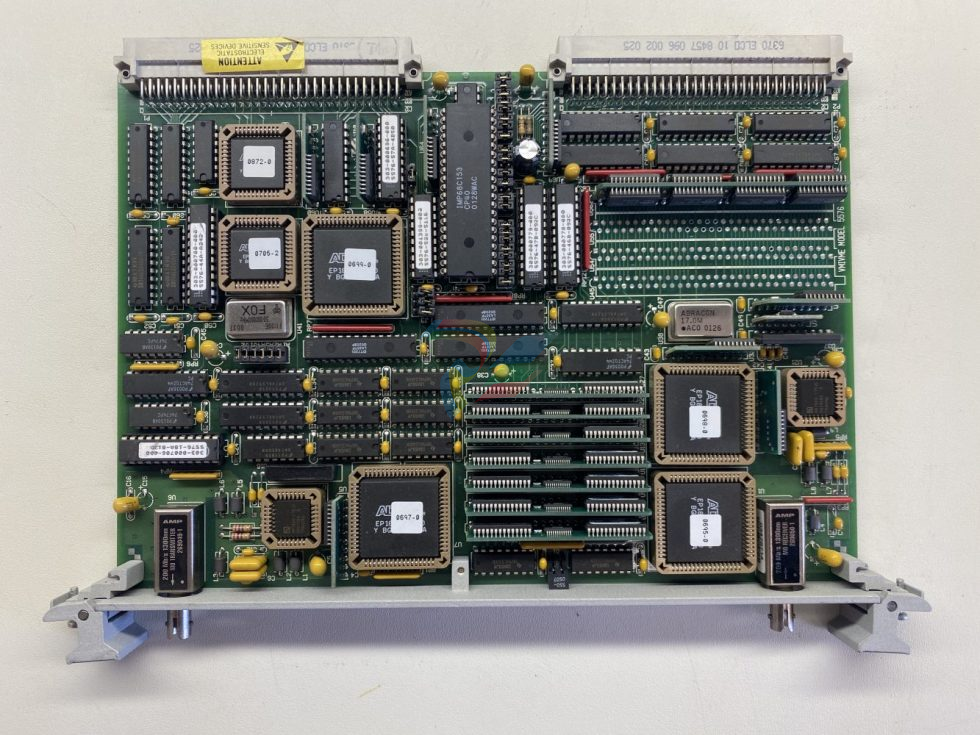
VMIVME-5576 is a
high-performance, multidrop VME-to-VME network. Data is
transferred by writing to on-board global RAM. The data is
automatically sent to the location in memory on all Reflective
Memory boards on the network.
PRODUCT OVERVIEW
—
The Reflective Memory
concept provides a very fast and efficient way of sharing data
across distributed computer systems.
VMIC’s VMIVME-5576 Reflective Memory interface
allows data to be shared between up to 256 independent
systems (nodes) at rates up to 6.2 Mbyte/s. Each Reflective
Memory board may be configured with 256 Kbyte to 1 Mbyte
of on-board SRAM. The local SRAM provides fast Read
access times to stored data. Writes are stored in local SRAM
and broadcast over a high-speed fiber-optic data path to other
Reflective Memory nodes. The transfer of data between nodes
is software transparent, so no I/O overhead is required.
Transmit and Receive FIFOs buffer data during peak data
rates to optimize CPU and bus performance to maintain high
data throughput.
The Reflective Memory also allows interrupts to one or
more nodes by writing to a byte register. These interrupt (three
level, user definable) signals may be used to synchronize a
system process, or used to follow any data that may have
preceded it. The interrupt always follows the data to ensure the
reception of the data before the interrupt is acknowledged.
The VMIVME-5576 requires no initialization unless
interrupts are being used. If interrupts are used, vectors and
interrupt levels must be written to on-board registers and the
interrupts armed.
Each node on the system has a unique identification
number between 0 and 255. The node number is established
during hardware system integration by placement of jumpers
on the board. This node number can be read by software by
accessing an on-board register. In some applications, this node
number would be useful in establishing the function of the
node.
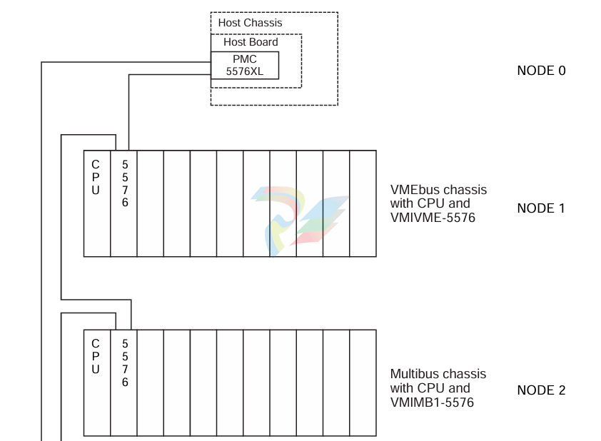
LINK ARBITRATION — The VMIVME-5576 system
is a fiber-optic daisy chain ring as shown in Figure 2. Each
transfer is passed from node to node until it has gone all the
way around the ring and reaches the originating node. Each
node retransmits all transfers that it receives except those that
it had originated. Nodes are allowed to insert transfers
between transfers passing through.
INTERRUPT TRANSFERS — In addition to
transferring data between nodes, the VMIVME-5576 will
allow any processor in any node to generate an interrupt on
any other node. These interrupts would generally be used to
indicate to the receiving node that new data has been sent and
is ready for processing. These interrupts are also used to
indicate that processing of old data is completed and the
receiving node is ready for new data.
Three interrupts are available. The user may define the
function, priority, and vector for each interrupt. Any
processor can generate an interrupt on any other node on the
network. In addition, any processor on the network can
generate an interrupt on all nodes on the network. Interrupts
are generated by simply writing to a single VMIVME-5576
register.
All data and interrupt command transfers contain the
node number of the node that originated the transfer. This
information is used primarily so the originating node can
remove the transfer from the network after the transfer has
traversed the ring. The node identification is also used by
nodes receiving interrupt commands. When a node receives
an interrupt command for itself, it places the identification
number of the originating node in a FIFO. Up to 512
interrupts can be stacked in the FIFO. During the interrupt
service routine, the identification of the interrupting node can
be read from the FIFO.
ERROR MANAGEMENT — Errors are detected by
the VMIVME-5576 with the use of the error detection
facilities of the TAXI chipset and additional parity encoding
and checking. The error rate of the VMIVME-5576 is a
function of the rate of errors produced in the optical portion
of the system. This optical error rate depends on the length
and type of fiber-optic cable.
Assuming an optical error rate of 10-12. the error rate of
the VMIVME-5576 is 10-10 transfers/transfer. However, the
rate of undetectable errors is less than 10-20 transfers/transfer.
When a node detects an error, the erroneous transfer is
removed from the system and a VMEbus interrupt is
generated, if armed.
The VMIVME-5576 can be operated in a redundant
transfer mode in which each transfer is transmitted twice. In
this mode of operation, the first of the two transfers is used
unless an error is detected in which case the second transfer
is used. In the event that an error is detected in both transfers,
the node removes the transfer from the system. The
probability of both transfers containing an error is 10-20. or
about one error every 372.000 years at maximum data rate.
PROTECTION AGAINST LOST DATA — Data
received by the node from the fiber-optic cable is error
checked and placed in a receive FIFO. Arbitration with
accesses from the VMEbus then takes place and the data is
written to the node’s SRAM and to the node’s transmit FIFO.
Data written to the board from the VMEbus is placed directly
into SRAM and into the transmit FIFO. Data in the transmit
FIFO is transmitted by the node over the fiber-optic cable to
the next node. Data could be lost if either FIFO were allowed
to become full.
The product is designed to prevent either FIFO becoming
full and overflowing. It is important to note the only way that
data can start to accumulate in FIFOs is for data to enter the
node at a rate greater than 6.2 or 3.2 Mbyte/s in redundant
mode. Since data can enter from the fiber and from the
VMEbus, it is possible to exceed these rates. If the transmit
FIFO becomes half-full, a bit in the Status Register is set and,
if armed, an interrupt is generated. This condition is an
indication to the software in the node that writes to the
Reflective Memory should be suspended until the FIFO
becomes less than half-full. If the half-full indication is
ignored and the transmit FIFO becomes full, then writes to the
Reflective Memory will be acknowledged with a bus error.
With VMEbus writes being blocked by the bus error, data
cannot overflow in the receive FIFO.
NETWORK MONITOR — There is a bit in a Status
Register that can be used to verify that data is traversing the
ring (that is, the ring is not broken). This can also be used to
measure network latency.
SPECIFICATIONS
Memory Size: 256 Kbyte, 512 Kbyte, or 1 Mbyte
Access Time:
400 ns (worst-case arbitration)
200 ns (best-case arbitration)
TRANSFER SPECIFICATION
Transfer Rate:
6.2 Mbyte/s (longword accesses) without redundant
transfer
3.2 Mbyte/s (longword accesses) with redundant transfer
COMPATIBILITY
VMEbus: This product complies with the VMEbus
specification (ANSI/IEEE STD 1014-1987. IEC 821 and
297), with the following mnemonics:
A32: A24: D32/D16/D08 (EO): Slave: 39/3D:09/0D
Form factor: 6U
Memory: Addressable on 256 Kbyte boundaries for
256 Kbyte memory option
Addressable on 512 Kbyte boundaries for 512 Kbyte
memory option
Addressable on 1 Mbyte boundary for 1 Mbyte memory
option
INTERCONNECTION
Cable Requirements: Two fiber-optic cables
Cable Length: 2.000 m maximum between nodes
Configuration: Daisy chain ring up to 256 nodes
PHYSICAL/ENVIRONMENTAL
Temperature Range: 0 to 55 °C, operating-40 to 85 °C, storage
Relative Humidity: 20 to 80 percent, noncondensing
Power Requirements: 5.0 A maximum at +5 VDC
MTBF: 142.400 hours (217F)
DATA TRANSFERS
Data written into the Reflective Memory is broadcast to
all nodes on the network without further involvement of the
sending or receiving nodes. Data is transferred from memory
locations on the sending nodes to corresponding memory
locations on the receiving nodes.
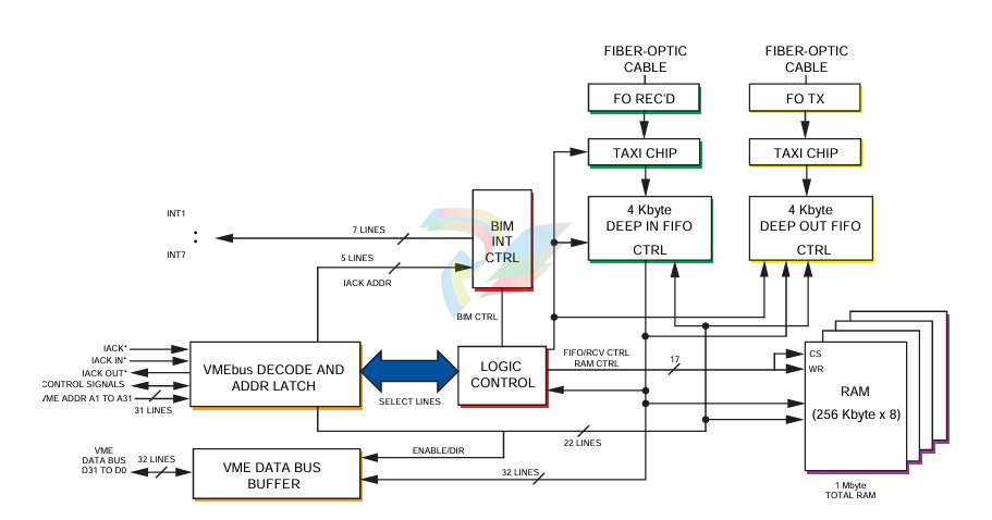
A functional block diagram of the VMIVME-5576 is
shown in Figure 1.
TRADEMARKS
The VMIC logo is a registered trademark of VMIC.
Other registered trademarks are the property of their
respective owners.
-
SAMSUNG SMBK-12 IOU Rack Backplane
-
SAMSUNG SMBK-08 IOU Rack Backplane
-
SAMSUNG SMPS-08 Rack Power Module
-
SAMSUNG SMCOM-08 Communication Expansion Card
-
SAMSUNG SMPI-8 Pulse Count Input Module
-
SAMSUNG SMTC-8 Thermocouple Input Module
-
SAMSUNG SMAOC-12 Analog Output Module (12CH)
-
SAMSUNG SMAOC-8 Analog Output Module (8CH)
-
SAMSUNG SMAIC-12 Analog Current Input Module (12CH)
-
SAMSUNG SMRTD-8 RTD Pt100 Temperature Input Module (8CH)
-
SAMSUNG SMAIC-8 Analog Input Module (8CH)
-
SAMSUNG SMDO-8 Digital Output Module (8CH)
-
SAMSUNG SMDI-8 Digital Input Module (8CH)
-
SAMSUNG SMCPU-08 Central Processing Unit Controller
-
Embedded MXM GPU Modules EGX-MXM-A4500 ADLINK
-
Embedded MXM GPU Modules EGX-MXM-AD2000 ADLINK
-
ADLINK Embedded MXM GPU Modules EGX-MXM-AD3500
-
ADLINK Embedded MXM GPU Modules EGX-MXM-AD5000
-
Embedded MXM GPU Modules EGX-MXM-AD ADLINK
-
Embedded MXM GPU Modules MXM-AXe ADLINK
-
ADLINK Embedded MXM GPU Modules EGX-MXM-BW500
-
Embedded MXM GPU Modules EGX-MXM-BW2000 ADLINK
-
ADLINK Embedded MXM GPU Modules EGX-MXM-BW4000
-
Embedded MXM GPU Modules EGX-MXM-BW5000 ADLINK
-
SAMSUNG SSAS-PRO SPTB-AI dedicated analog input terminal board
-
SAMSUNG SSAS-PRO SPTB-DO dedicated digital output terminal board
-
SAMSUNG SSAS-PRO SPTB-DI dedicated terminal board
-
SAMSUNG SSAS-PRO SPBK-X32-12 Heavy-duty 8-slot system chassis backplane
-
SAMSUNG SSAS-PRO SPBK-X32-08 Heavy-duty 8-slot system chassis backplane
-
SAMSUNG SSAS-PRO SPSU-X32 heavy-duty rack-mounted
-
SAMSUNG SSAS-PRO SPIRU-16 versatile universal mixed I/O module
-
SAMSUNG SSAS-PRO SPRI-16 RTD Temperature Input Module
-
SAMSUNG SSAS-PRO SPAO-8 Analog Output Module
-
SAMSUNG SSAS-PRO SPAI-16 Analog Input Module
-
SAMSUNG SSAS-PRO SPRDO-16 Relay digital output module
-
SAMSUNG SSAS-PRO SPDO-16 (Transistor Digital Output Module)
-
SAMSUNG SSAS-PRO SPDI-24 high-density digital input module
-
SAMSUNG SPDI-16 (Digital Input Module)
-
ADLINK 3U Enclosures & Systems AD-3100
-
Power Supplies cPS-H300S/AC ADLINK
-
CPCI Serial Peripheral cPCI-A3H10 ADLINK
-
ADLINK CPCI Serial Peripheral cPCI-A3XMC
-
CPCI Serial Peripheral cPCI-A3H20 ADLINK
-
CPCI Serial Peripheral cPCI-A3MXM ADLINK
-
ADLINK CPCI Serial Peripheral cPCI-A3COM
-
ADLINK CPCI Serial Peripheral cPCI-A3USB
-
ADLINK CPCI Serial Peripheral cPCI-A3ETH
-
CPCI Serial Peripheral cPCI-A3CAN ADLINK
-
3U CompactPCI Serial Blades cPCI-A3525 Series
-
3U CompactPCI Serial Blades cPCI-A3535 Series ADLINK
-
CompactPCI Backplanes cBP-6402 ADLINK
-
ADLINK CompactPCI Backplanes cBP-6402R
-
ADLINK CompactPCI Backplanes cBP-6105R
-
CompactPCI Backplanes cBP-6405R ADLINK
-
CompactPCI Backplanes cBP-6108F ADLINK
-
CompactPCI Backplanes cBP-6108R ADLINK
-
CompactPCI Backplanes cBP-6014R ADLINK
-
ADLINK 6U Enclosures & Systems cPCIS-6130R
-
ADLINK 6U Enclosures & Systems cPCIS-6230R/ 6240R Series
-
ADLINK 6U Enclosures & Systems cPCIS-6235R
-
ADLINK 6U Enclosures & Systems cPCIS-6400X Series
-
ADLINK 6U Enclosures & Systems cPCIS-6400U Series
-
ADLINK 6U Enclosures & Systems cPCIS-6418U
-
ADLINK 6U Enclosures & Systems cPCIS-3300BLS
-
ADLINK 6U Enclosures & Systems cPCIS-3320/AC
-
ADLINK Power Supplies cPS-H640/AC
-
ADLINK Power Supplies cPS-H640/48
-
ADLINK 6U Rear Transition Modules cPCI-R6100 Series
-
ADLINK 6U Rear Transition Modules cPCI-R6002 Series
-
ADLINK 6U Rear Transition Modules cPCI-R6600 Series
-
ADLINK 6U CompactPCI 2.0 Blades cPCI-6660
-
ADLINK 6U CompactPCI 2.0 Blades cPCI-6636(KL) Series
-
ADLINK 6U CompactPCI 2.0 Blades cPCI-6640 Series
-
ADLINK 6U CompactPCI 2.0 Blades cPCI-6540 Series
-
ADLINK CompactPCI Backplanes cBP-3064
-
ADLINK CompactPCI Backplanes cBP-3213PR
-
ADLINK 3U Enclosures & Systems cPCIS-2500 Series
-
ADLINK 3U Enclosures & Systems cPCIS-2630 Series
-
ADLINK 3U Enclosures & Systems cPCIS-2632 Series
-
ADLINK 3U Enclosures & Systems cPCIS-2642 Series
-
ADLINK U Enclosures & Systems cPCIS-2633 Series
-
ADLINK U Enclosures & Systems cPCIS-ET1100 Series
-
ADLINK Power Supplies cPS-H325/AC
-
ADLINK Power Supplies cPS-H325/48
-
ADLINK Power Supplies cPS-H325/110
-
ADLINK Power Supplies cPS-H325/24
-
ADLINK PCI-7841/cPCI-7841 Dual-port Isolated CAN Interface Cards
-
ADLINK Peripherals & Accessories cPCI-3548
-
ADLINK Peripherals & Accessories cPCI-8301
-
ADLINK Peripherals & Accessories cPCI-3W10
-
ADLINK Analog Output cPCI-6208/6216 Series
-
ADLINK Multi-Function DAQ cPCI-9116
-
ADLINK 3U CompactPCI Blades CT-3620
-
ADLINK 3U CompactPCI Blades cPCI-3620
-
ADLINK 3U CompactPCI Blades cPCI-3620
-
ADLINK 3U CompactPCI Blades cPCI-3630
-
ADLINK 3U CompactPCI Blades cPCI-3640 Series
-
3U CompactPCI Blades cPCI-3520 Series
-
ADLINK IMB-M42H ATX Motherboards
-
Adlink PCIe-GIE74 /PCIe-GIE74V Frame Grabbers / Video Capture Cards
-
ADLINK USB-1605 Removable screw terminal blocks or high-density D-Sub
-
Adlink ETX-NR667-L7400/LXE ETX Module
-
ADLINK NuPRO-842LV/P industrial control motherboard
-
ADLINK cPCI-8994 Serial Communication
-
ADLINK / PCI-7432 Digital I/O
-
ADLINK IEC-915GV Compact industrial-grade fanless embedded system
-
ADLINK ADLINK, PLX / PCI-7296 Digital I/O
-
ADLINK HPCI-14S12U 0040 Backplane Selection Guide
-
ADLINK MXE-5500 /MXE-5501/M16G (G) Fanless Embedded Computer
-
Adlink Multi-Function DAQ PCI-9112
-
ADLINK NuPRO-852LV Control Board
-
ADLINK CompactPCI cPCI-7432R Digital I/O Module
-
ADLINK NUPRO-E320LV PICMG Single Board Computers
-
ADLINK PICMG Single Board Computers NuPRO-E72
-
ADLINK PICMG Single Board Computers NuPRO-865
-
Vibro-Meter Rack VM600SYSMK2-ABE04x 6U 19-inch rack Mk2 system
-
Vibro-Meter Relay expansion RLC16 Mk2 SIL2 (single card) 600-044L
-
Vibro-Meter Relay expansion RLC16 Mk2 SIL2 600-04
-
Vibro-Meter Relay expansion RLC16 Mk2 600-045L
-
Vibro-Meter Relay expansion RLC16 Mk2 600-045
-
Vibro-Meter I/O interface card IOCN Mk2 600-051
-
Vibro-Meter CPU controller CPUM Mk2 600-050
-
Vibro-Meter I/O interface card IOC10 Mk2 (rear card) 600-046
-
Vibro-Meter Temperature / Analog Acquisition AMC10 Mk2 600-042
-
Vibro-Meter I/O interface card IOC4 Mk2 600-043
-
Vibro-Meter Protective measuring card MPC4 Mk2 SIL2 601-041-A10
-
Vibro-Meter Protective measuring card MPC4 Mk2 601-041-A0
-
Vibro-Meter PSU-VM600 VM600 Rack Power Module

Add: High-tech Software Park, Xiamen City, Fujian Province
Mobile: +86-17750019513(WhatsApp)
Email: yy4291644@gmail.com
Website: https://www.abb-sis.com
.jpg)
.jpg)
.jpg)
.jpg)
.jpg)
.jpg)

-
SAMSUNG SMBK-12 IOU Rack Backplane
-
SAMSUNG SMBK-08 IOU Rack Backplane
-
SAMSUNG SMPS-08 Rack Power Module
-
SAMSUNG SMCOM-08 Communication Expansion Card
-
SAMSUNG SMPI-8 Pulse Count Input Module
