

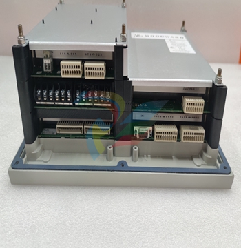
WOODWARD EGCP-3 Engine Generator Control Package LS (Load Sharing)
General Information
Introduction
This manual describes the Woodward EGCP-3 Engine Generator Control
Package, Load Sharing (LS) model, part number 8406-113. It provides
description, operation, tuning, and troubleshooting information for EGCP-3 digital
controls. The details on installation, wiring, communication, Regulatory Notes
and Warnings are in the EGCP-3 Installation Manual 26122. The EGCP-3 LS is
intended for power generator applications where multiple control/generators will
supply an isolated bus, or operate in parallel with a Mains (Utility) bus. The
EGCP-3 can perform engine start/stop sequencing. For isolated load operation,
the control will operate in isochronous speed control. For a multiple engine bus,
up to 16 generators can share load, operate in BaseLoad, or process control
modes.
The generator should be equipped with a sync check relay, circuit breaker, and other fast-acting protective relays as required by local codes and practices to protect against damage to the generator with possible personal injury, loss of life, or property damage.
The overspeed shutdown device, sync check relay, circuit breaker, and other fast-acting protective relays must be totally independent of the prime mover control system. An overtemperature or overpressure shutdown device may also be needed for safety, as appropriate.
Protective Earth (PE) must be connected to the termination point on the backside of the unit next to the label with the symbol (or 1 of 3 other like termination points without label) to reduce the risk of electric shock. This connection will be made using a thread-forming screw. The conductor providing the connection must have a properly sized ring lug and wire larger than or equal to 4 mm² (12 AWG).
HIGH VOLTAGE—The calibration and checkout procedure should only be performed by authorized personnel knowledgeable of the risks posed by live electrical equipment.
The installation must include the following:
The power supply mains should be properly fused according to the installation instructions and the appropriate wiring requirements.
A switch or circuit breaker must be included in the building installation in close proximity to the equipment and within easy reach of the operator, and must be clearly marked as the disconnecting device for the equipment. The switch or circuit breaker will only remove power to the unit—hazardous voltages may still be connected to other terminals on the unit.
Application and Functions
The EGCP-3 control is a microprocessor-based generator load control designed
for use with a separate speed control and an automatic voltage regulator to
provide synchronizing, paralleling, loading and unloading. All transitions between
EGCP-3 functions are coordinated to provide smooth operation.
EGCP-3 LS Functions:
Display/Keypad Interface for local setup/monitoring
Engine Start/Stop Sequence Control
Monitor of Generator and Bus power
Unit sequencing and individual unit protection
Engine Protection and Monitoring
Synchronizer with speed, phase, voltage matching, token passing for dead bus closure, and multiple unit synchronizing
KW Control with automatic generator loading and unloading for bumpless load transfer
Droop, BaseLoad, Isochronous, and Isochronous load sharing control capability
Frequency and voltage trimming in Isochronous mode
Communication bus between Master Control and other LS units
Master/Slave Process control for cogeneration, import/export, pressure control, or other processes
KVAR/PF Control and bus /PF sharing
Individual generator stable timing
Built in diagnostics
Generator and Bus Protective Relaying
Generator Power & Energy Metering
Modbus® * and ServLink communications for remote HMI/PLC connections
HMI/Front Panel Display
The EGCP-3 has a keypad and two 4-line display panels on the front cabinet
mounted chassis. The display can be used to configure and set up the control for
site specific requirements. The display is also used in normal operating service to
monitor operation and view alarm data. All functions performed and parameters
monitored by the front panel are also available through the three serial ports.
These ports can be configured to use Woodward Watch Window software, an
external HMI and Modbus communication, or ServLink DDE software.
Engine Control
The EGCP-3 control performs stop and start logic for both gas and diesel
reciprocating engines. The starting logic includes: pre-glow capability, separate
enabling for ignition, fuel pump/FSOV logic, and a configurable pause at idle. The
engine stop function includes: controlled cooldown, soft shutdown logic and
emergency stop logic. The start and stop logic includes closing and opening of
generator breaker. Typical protections such as over speed, coolant temperature,
oil pressure, and battery voltage are also provided. Configurable digital and
analog fault inputs are provided for use with temperature, pressure, or level
switches. All the faults may be disabled when not needed. In addition to
automatic modes, Manual start and stop for the engine is possible. The circuit
breaker can be closed manually to load the generator in the selected load control
mode (Process, Droop, BaseLoad, Isochronous) when manual control is desired.
Synchronizer
The EGCP-3 control uses digital signal processing techniques to derive both true
RMS voltages and relative phase of the fundamental frequencies of the bus and
generator voltage wave forms. Digital signal processing techniques offer
significantly improved measurement accuracy in the presence of waveform
distortions, particularly since the phase measurement does not depend on zero
crossings of the waveforms.
Either phase matching or slip frequency synchronizing may be selected. Phase matching method controls the engine speed to give zero speed error and minimal phase error between the generator and bus; this provides rapid synchronizing for critical standby power applications. Slip frequency synchronizing guarantees a fixed speed difference between generator and bus. This insures the generator to be faster than the bus and initial power flow is out of the machine for larger generators. For both synchronizing methods, the EGCP-3 control uses actual slip frequency and breaker delay values to anticipate a minimum phase difference between bus and generator at actual breaker closure.
The synchronizer can sense a dead local bus and close the generator circuit breaker automatically when safe to do so. The network communication between EGCP-3 control assures that multiple generators cannot close simultaneously onto a dead bus.
There are four synchronizer modes of operation: Run, Check, Permissive, Off. The mode can be selected through Watch Window, the front panel display, or Modbus. The last mode selected by any of these interface methods will be the mode of operation.
Additional synchronizer features include: voltage matching, time delayed automatic multi-shot reclosing, and a synchronizer timeout alarm. Raise and lower inputs can be used to manually adjust speed for manual synchronizing. Voltage raise and lower inputs can be used to manually adjust voltage for manual voltage matching. Each of these features may be enabled or disabled during setup.
Load Control
When the generator circuit breaker is closed, the LS model is in Isochronous and
will Load Share with other units also connected to the bus. The speed bias output
will control the load of each engine by slight changes to the speed control’s
speed reference. When the breaker is open, the EGCP-3 will be in droop
operation. Another mode of Load control is BaseLoad; it begins at breaker
closure when the load control function takes control of the EGCP-3 speed bias
output directly from the synchronizer. The matching of synchronizer slip
frequency to initial load (unload trip level) can result in a bumpless transfer to
load control. On command, the adjustable ramp allows smooth, time-controlled
loading into Load Sharing, BaseLoad, or process control. A ramp pause switch
input allows holding of the load ramp for warm-up or other purposes. Process
Control is a derivative of BaseLoad operation. In this control mode, one genset
may be assigned as a master, to control the loading of other gensets on the bus.
The EGCP-3 control provides switch inputs to allow raising or lowering the internal BaseLoad reference. The control also provides a 4–20 mA (or 1–5 Vdc) analog input for remote load setpoint, if desired. The load reference can also be set through a Modbus or ServLink DDE communication interface.
When unloading, an adjustable unload ramp provides time controlled unloading to the unload trip level. When load reaches the unload trip level, the control will hold the load at the unload value, the breaker can then be opened manually to remove the genset from service. The ramp pause switch can be used to stop the load ramp at its present value for cool-down or other purposes.
The load and unload ramps also provide smooth transition between BaseLoad and process control any time the operating mode is changed.
The EGCP-3 control includes several additional load control features:
Simple load droop operation provides safe operation in parallel bus applications in the event of a circuit breaker aux contact failure.
Isochronous operation when the bus is isolated.
Adjustable load switch output with independent pick-up and drop-out points provides a signal when the specified load is exceeded.
Process Control
A cascade process controller is provided for cogeneration, import/export control,
pond level maintenance, pressure maintenance, or other application. An
adjustable bandwidth input filter, flexible controller adjustments, an adjustable
deadband, and direct or indirect control action, allow the process control to be
used in a wide variety of applications.
A 4–20 mA (or 1–5 Vdc) process transmitter provides the process signal to the EGCP-3 control. The control includes an internal digital process reference which may be controlled by raise and lower switch contact inputs or by an external 4 20 mA (or 1–5 Vdc) process reference, or by a Modbus or ServLink communication interface. The output of the process control provides the cascade load reference to the BaseLoad control.
Adjustable ramps allow smooth entry to or exit from the process control mode. When the process control mode is selected, an adjustable ramp moves the load reference in a direction to reduce the process control error. When the error is minimized, or the reference first reaches either the specified high or low load pick-up limits, the process controller is activated. When unloading from the process control, an adjustable unload ramp provides time controlled unloading to the unload trip level. When load reaches the unload trip level, the EGCP-3 control automatically issues a breaker open command to remove the generator set from the system. The ramp pause switch input allows holding of the load ramp for cool-down or warm-up purposes.
Additional functions include selectable and adjustable process high and low limit switches and alarm activation.
When multiple gensets and EGCP-3 LS controls are connected to a bus in process control mode one unit is automatically assigned as the “Process Master”. It’s process control loop then dictates through the LON network the load levels of other gensets on the bus.
VAR/PF Control
The VAR/PF functions control the reactive power component of the generator in
parallel systems. The reactive load mode can be configured for VAR or Power
Factor control. The controller compares the reactive load on the generator with
an adjustable internal reference and makes corrections to the setpoint of the
Automatic Voltage Regulator (AVR) until the desired reactive power is obtained.
The reactive power level can be maintained while also controlling real load
through the generator breaker. The analog voltage bias output can be directly
connected to compatible voltage regulators. The control also has raise and lower
contact outputs to activate a voltage regulator MOP when an analog input is not
provided on the AVR. The EGCP-3 control has a selectable voltage range alarm
that is activated if the analog output to the voltage regulator reaches high or low
saturation. The EGCP-3 control also has selectable and adjustable high and low
voltage limit switches and alarm outputs.
The EGCP-3 control provides switch inputs to allow raising or lowering the generator voltage reference. The control also provides a 4–20 mA (or 1–5 Vdc) analog input for kVAR/PF setpoint control, if desired. The kVAR/PF reference can also be set through a Modbus or ServLink DDE communication interface.
While the EGCP-3 is controlling unit load to accomplish real load (kW) sharing, the voltage of the generators in parallel will be controlled to accomplish equal Power Factor levels of each generator.
ATS Control
ATS functions are not included in the LS model of EGCP-3. A Master Control (MC) is used to control the mains circuit breakers and local bus circuit breakers to perform ATS functions.
Peaking and Demand Operation
The LS model does not have Peaking and Demand functions. This function is
provided from an MC control that provides the interface with the mains(utility) and
LS units.
Genset Sequencing
While the details of how to start and stop a genset is determined by the Engine
Control sequence, when to initiate a start or stop is the function of the sequence
configuration. The starting and stopping of Gensets is closely associated with the
configuration of the system bus structure and genset characteristics. All EGCP-3
LS and EGCP-3 MC controls on a common network communicate their operation
status and the mains and bus status over a Echelon Network (LON). Systems
with up to 16 gensets, and/or four local bus segments, and/or two mains
connections for a split bus arrangement can be configured. When automatic
connection(s) to the mains is configured an EGCP-3 MC connected to the LON
network is required. The user can configure the criteria used to start and stop
genset(s) and the priority of which genset is the next to start or stop.
A typical start/stop sequence would be:
When the units on a bus segment are above a configured Maximum Load Level or above their 100% Load Level, a start command will be given to the next scheduled unit.
When the units on this bus segment are below a configured Minimum Load
Level, a stop command will be given to the next scheduled unit.
Power and Energy Metering
The digital signal processing techniques are used to provide significantly improved accuracy and speed of response over conventional analog measurement techniques. Accuracy is improved using rapid sampling of the voltage and current signal waveforms and developing a true RMS measurement. Measuring true RMS power allows optimal accuracy, even in the presence of power line distortions.
The PowerSense board receives the PT and CT inputs for both the generator and bus for calculation of parameters for the EGCP-3 to use in system control. The algorithms used are based on IEEE 1459-2000. For the generator and bus the following parameters are provided: Hz, Vac, Amps, W, VA, VAR, PF, Phase, Voltage harmonics, Current harmonics, Negative Phase Sequence Voltage, Negative Phase Sequence Current.
Available for selection at the 4–20 mA analog outputs: Synchroscope, Generator metering, Mains metering
Protective Relaying
The PT and CT inputs were designed for accurate voltage and current monitoring
in applications of display and control. They are not designed for high speed,
sub-cycle, or cycle-to-cycle protective relaying though time delay protective
relaying can be used.
The EGCP-3 should not be used as the only means for detecting
voltage or current disturbances, dead bus conditions, or overcurrent
conditions. The generator should be equipped with a sync check relay,
circuit breaker, and other fast-acting protective relays as required by
local codes and practices to protect against damage to the generator
with possible personal injury, loss of life, or property damage. The
sync check relay, circuit breaker, and other fast acting protective
relays must be totally independent of the EGCP-3.
Alarms can be configured for generator and bus protective relay (i.e. Reverse
power, Under Voltage) functions. Time delay, and separate warning and trip
thresholds can be set. A complete list of protective relay functions available is
given in Chapter 3. Current based protections are implemented using the
ANSI/IEEE C37.112 Very Inverse curve.
Communications
The EGCP-3 includes three serial ports for simultaneous connection to remote
HMI, PLC, remote control and monitoring equipment. The remote monitoring and
interface can be by Modbus tools or Woodward ServLink tools. Configuration of
the EGCP-3 may be done from the front panel or through a serial port using
Woodward Watch Window software. The Watch Window software allows easy
configuration in a Windows environment.
Woodward 2301A Load Sharing Speed Control 9905-377
Woodward AMG 2 Engine/Generator Controller (8440-1273G)
Woodward 8272-683 Digitale Riferimento Unit
Woodward 8272-683 Digital Reference Unit
Woodward 8272-683 Numrique RF unit
Woodward 8272-683 Digital Reference Unidad
Woodward 8272-653 electric operated potentiometer sn.10067.1006666666686
Woodward 5484-721 motor
Woodward EPS1000 engine status light
Woodward 8270-990 signal converter
Woodward Motor Overload Relay 1765-825 4
Woodward 8901-037 booster servo motor
Woodward 9905-021
Woodward 9905-021
Woodward 8270-1082
APECS driver 0175-24ASLS SA-4573-24 24VDC
APECS actuator 0175-24 ASLS SA-4573-24 24VDC
Woodward SPM-D1145B/LSXR
Woodward MFR13/MFR13
Woodward MFR 1371M/MFR1371M
Woodward DYN1-10654-000-0-24
Woodward BN1-400/BN1400
Woodward 9907-866/9907866
Woodward 9907-018/9907018
Woodward 9907-014/9907014
Woodward 9905-384/9905384
Woodward 9905-090/9905090
Woodward 8440-2050/84402050
Woodward 84401614/84401614
Woodward 8406-113/8406113
-
BECKHOFF AX5106-0000-0200 | Digital Compact Servo Drives 1-channel
-
BECKHOFF C3620-0000 INDUSTRIAL COMPUTER (MOTORSHELVES)
-
Beckhoff EK1960-0000 TwinSAFE Compact Controller
-
Beckhoff C6930-0050 Control Cabinet Industrial PC
-
Beckhoff CX1001-0111 Embedded PC CPU Module
-
Beckhoff C6017-0020 | Ultra-compact Industrial PC
-
Beckhoff EK1322 | 2-port EtherCAT P junction with feed-in
-
Beckhoff CP2219-0010 Panel
-
BECKHOFF C6015-0020 ULTRA COMPACT INDUSTRIAL PC
-
BECKHOFF CX2030-0120/Standard CPU Module Embedded PC Windows PLC controller
-
Beckhoff CP7721-1090-0020 Panel PC
-
Beckhoff PC CPU Module CX5130-0175
-
Beckhoff C6920-0050 Control Cabinet
-
Beckhoff EL6631 EtherCAT 2-Port Communication Interface, Profinet RT Controller
-
Beckhoff CP6202-0001-0060 touch screen panel PC
-
Beckhoff CP3916-1002-0000 Multi-Touch Control Panel
-
Beckhoff EP1809-0021 | EtherCAT Box, 16-channel digital input, 24 V DC, 3 ms, M8Preferred type
-
Beckhoff CX8190 PLC Embedded Industrial PC Ethernet Controller
-
Beckhoff CX2100-0914 Power Supply for External
-
Beckhoff Automation CP6906-0001-0000 HMI
-
Beckhoff EP7342-0002 Module
-
Beckhoff CX1020-0112 / CX1100-0910 / CX1020-N010 / CX1100-0003 Windows CPU
-
Beckhoff EP7211-0034 EtherCAT Box 1 Channel Motion Interface
-
Beckhoff C6240-0030 Control cabinet Industrial PC
-
beckhoff motherboard CB1052-0004 CB1052-0004
-
Beckhoff AX2006-AS Servo Drive / Variable Frequency Drive
-
BECKHOFF CP6207-0001-0020 NSMP
-
Beckhoff C6930-1142-0060 Industrial Computer
-
Beckhoff FC7501-0000 interface card
-
Beckhoff CX5140-0175 Embedded PC PLC CPU CX5140 Industrial Controller
-
Beckhoff CP7802-1100-0010 High-End IP65 Control Panel with DVI/USB Extended Interface
-
BECKHOFF CP3716-1058-0010 CONTROL PANEL
-
Beckhoff AX8108-0000 Single-Axis Module
-
Beckhoff CU8851-0000 | USB extension, USB Extended 2.0 receiver box
-
Beckhoff C6017-0030 | Ultra-compact Industrial PC
-
Beckhoff CX1001-0120/CX10010120.cx1000-n001.cx1000-n000 System Overview
-
Beckhoff CPU Module CX5140-0155/4GB CPU Module
-
Beckhoff CP6533-0001-005: Built-in Panel PC with High-Definition Multi-Touch Control
-
Beckhoff EL5042 | EtherCAT Terminal, 2-channel encoder interface, BiSS® C
-
Beckhoff C6920-1080-0040: Premium Control Cabinet Industrial PC
-
Beckhoff C6920-0060 | Control cabinet Industrial PC
-
Beckhoff Embedded-PC CX5010-1121
-
Beckhoff CB3050-0010 Mainboard Motherboard
-
Beckhoff PLC module CX1020-0000
-
Beckhoff Compact Servo Amplifier AX5112-0000-0200
-
Beckhoff CP7812-1056-0010 15" Multitouch Display Control Panel
-
Beckhoff CX5120-0115 /2GB Controller Module
-
Beckhoff CP7201-1000-0000 Industrial Panel PC
-
Beckhoff Servo Motor AM8061-0JH1-0000
-
BECKHOFF CP6503-0001-0050 Built-in Panel PC
-
Beckhoff CP3919-0010 Display G190ETN01.2 19" PCT V04. Multi-touch Control Panel
-
Beckhoff CX5110-0112-9020/000368201 Embedded PC Intel Atom Processor
-
Beckhoff AX8206-0000-0000 | Dual-axis module
-
Beckhoff Nail Operating Terminal CP7032-1031-0010
-
Beckhoff AM8042-0EH1-0000 Servomotor 4.10 Nm (M0), F4 (87 mm)
-
Beckhoff EK9300 | PROFINET RT Bus Coupler
-
Beckhoff CP3224-0020 Multitouch-Panel-PC
-
Beckhoff CP2712-0000 12.1" 24VDC Touch Screen WMD0
-
BECKHOFF CX5240-0195 / 0000289234 Embedded PC 40 GB CFast Card
-
Beckhoff CP6932-1000-0000 Control Panel
-
BECKHOFF CX5120-0121 PLC Module
-
Beckhoff EL3218 | EtherCAT Terminal, 8-channel analog input
-
Beckhoff EL3218 | EtherCAT Terminal, 8-channel analog input
-
Beckhoff C6640-0050 | Control cabinet Industrial PC
-
Beckhoff Cx5130-0120/4GB Embedded-PC
-
BECKHOFF CX2030-0122 PLC PROCESSOR
-
BECKHOFF CX5020-0122 Controller Module
-
Beckhoff CP3915-0000 Multitouch Panel
-
BECKHOFF EL3014 | EtherCAT Terminal
-
BECKHOFF Industrial Computer c6920-1057-0030
-
Beckhoff CX5130-0141/4GB CX5130-0141 Embedded PC
-
Beckhoff C6240-1052-0040 4-086-06-3073 Industrial Computer
-
Beckhoff CX5140-0135 /4GB High-Performance Embedded Industrial PC
-
Beckhoff C6515-1001-0000 Industrial PC
-
Beckhoff AX5103-0000-0200 - Digital Compact Servo Drives
-
Beckhoff CX2030-0130-1003/4GB Basic CPU module
-
Beckhoff AX8620-0000 Power Supply Module
-
Beckhoff CX9020-0111 module with
-
Beckhoff EL7332 PLC Module
-
BECKHOFF CP7709-0001-0020 HMI
-
Beckhoff CX5120-0155/2GB Embedded PC
-
BECKHOFF CP7037-1037-0010 OPERATOR INTERFACE TOUCHSCREEN
-
Beckhoff EK9000 | ModbusTCP/UDP Bus Coupler
-
Beckhoff Touch Panel Screen CP6020 -0000-0000
-
Beckhoff CX2020-0121 Module FAST Shipping
-
Beckhoff CX2030-0125 Basic CPU Module
-
Beckhoff CP3918-0000 Multi-Touch 18.5" Control Panel
-
Automotion LC4A00010 DC BL Motor Control, ATS, Sub Assy, SCP, 115VAC,
-
500T-115VAC - VAS ENGINEERING - DORIC 500 SERIES DIGITAL TEMP INDICATOR
-
Honeywell X-DCS2000/EN Digital Integrated System Manager 50/60Hz 100-240V #4
-
Kollmorgen S60600 Servostar600 606-Fan 4 kVA, 6 A, 3 X 230 - 480 V
-
ABB XZ C828 A101 Didt Dioder Snubber 3BHE039453R0101
-
ABB 3BHB027232R0001 1-Phase Charging Transformer
-
ABB 3BHE006412R0101 Circuit Board UFC762AE101
-
ABB XVC770BE101 3BHE021083R0101 Circuit Board
-
ABB 3BHE021887R0101 UBCC717BE101 Board 3BHB002751R0102
-
ABB 3BHE032593R0001 Isolated Power Supply
-
ABB 3BSC610023R0001 POWER SUPPLY SD812
-
Beckhoff C6650-0060 | Control cabinet Industrial PC
-
Beckhoff CP2916-0000 Industrial HMI Display Panel
-
Beckhoff AM8053-0L2B-0000 Servomotor 15.4 Nm (M0), F5 (104 mm)
-
Beckhoff CP6202-0001-0020 Industrial Panel PC
-
Beckhoff CX2020-0120 Plc Module
-
Beckhoff CX1010-0111 BASIC CPU MODULE
-
Beckhoff C6017-0010 | Ultra-compact Industrial PC
-
BECKHOFF CX2040-0155 Plc Module
-
Beckhoff CX5120-0125 Embedded PC
-
BECKHOFF C6930-0040 INDUSTRIAL CONTROL COMPUTER
-
Beckhoff CP6907-0001-0000 Economy Built-in Control Panel
-
Beckhoff CP2912-0000 Multi-Touch Built-In Control Panel
-
Beckhoff C6015-0010 Ultra-Compact Industrial PC
-
Beckhoff CX5130 | Embedded PC with Intel Atom® E3827
-
Beckhoff C6030-0060 Ultra-Compact Industrial PC
-
OMRON 3G3XV-A2007 3G3XV-A2007-NEV2
-
Omron NJ1019000 NJ1 programable logic controller
-
OMRON C120-LK202-EV1/C120LK202EV1
-
OMRON C200H-AD003 PLC
-
OMRON C200H-CPU23-E COIL 24VDC PLC
-
Omron C200HG - C200H-ID212- C200H-OC226 C200HW-BC101 PLC Base Unit
-
OMRON C200H-OC222(Output Unit),C200H-PS211(Power Supply Unit),SP001 Module Rack
-
OMRON C200H-RT201 PROGRAMMABLE CONTROLLER
-
OMRON C200HS-CPU01-E SYSMAC PROGRAMMABLE CONTROLLER
-
OMRON C200H-SNT31 C200H Programmable Controllers
-
OMRON C200HW-MC402-E Motion control unit
-
OMRON C500-CT012 PLC
-
OMRON C500-NC103-E PLC
-
OMRON C500-NC222-E PLC
-
OMRON C500-PRW05-V1 PLC
Add: High-tech Software Park, Xiamen City, Fujian Province
Mobile: +86-17750019513(WhatsApp)
Email: yy4291644@gmail.com
Website: https://www.abb-sis.com
.jpg)
.jpg)
.jpg)
.jpg)
.jpg)
.jpg)

-
BECKHOFF AX5106-0000-0200 | Digital Compact Servo Drives 1-channel
-
BECKHOFF C3620-0000 INDUSTRIAL COMPUTER (MOTORSHELVES)
-
Beckhoff EK1960-0000 TwinSAFE Compact Controller
-
Beckhoff C6930-0050 Control Cabinet Industrial PC
-
Beckhoff CX1001-0111 Embedded PC CPU Module
