

Woodward 723PLUS Digital Control
723PLUS Digital Control
9906-619. 9906-620. 9906-700
This manual describes the Woodward 723PLUS Digital Control hardware,
9906-619 (low voltage), 9906-620 (high voltage), and 9906-700 (modified
actuator filtering, low voltage).
Application
The 723PLUS Digital Control can be programmed to suit applications requiring
two magnetic pickups (MPUs) or proximity switches (e.g. for torsional filtering) as
the hardware includes two speed inputs. It also includes four analog inputs, three
analog outputs, eight discrete inputs and three discrete outputs, all of which can
be programmed to satisfy the application. The control can be used in load
sharing systems as it contains circuitry and connections to support this.
The two LON®* channels can be used to support Woodward LonTalk®* or
LinkNet® input/output nodes control functions.
*—LON and LonTalk are trademarks of Echelon Corporation.
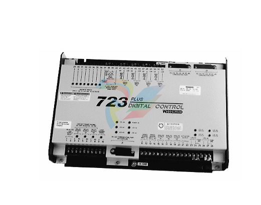
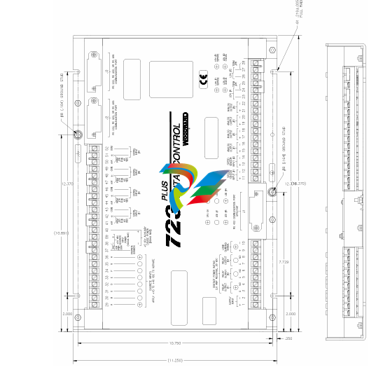
The 723PLUS control (Figure 1-1) consists of a single printed circuit board in a
sheet-metal chassis. Connections are via three terminal strips and three 9-pin
subminiature D connectors.
Control Options
The 723PLUS control requires the following power supply input voltages, with 40
watts as the nominal power consumption at rated voltage:
18–40 Vdc (24 or 32 Vdc nominal)
90–150 Vdc (125 Vdc nominal)
Discrete input voltages provide on/off command signals to the electronic control.
Each discrete input requires 10 mA at its 24 Vdc nominal voltage rating (for 24
volt switching logic).
Other control options are:
proximity switch input for speed signal frequencies below 100 Hz (see
NOTE)
0–1 mA for meter drivers
tandem actuator outputs
dual actuator outputs (0–200 mA)
The control may be used with either proximity switches (see NOTE) or magnetic
pickups. The minimum frequency for steady state speed control is 30 Hz. For
more information see Control Specifications (inside back cover).
723PLUS Digital Control Accessories
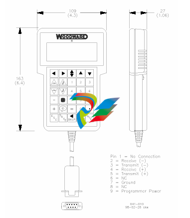
Hand Held Programmer (Figure 1-2), part number 9907-205. can be used
for adjusting the 723PLUS control. It plugs into serial port J1 of the control.
This part is EU Directive compliant.
SPM-A Synchronizer, for synchronizing the generator phase to that of the
power bus. The synchronizer generates a close generator breaker signal to
parallel the generator with the power bus.
Power Output Sensor, for load sharing or droop operation in mechanical
load applications.
Real Power Sensor, for load sharing or droop-parallel generator
applications.
Digital Synchronizer and Load Control (DSLC™) for generator load
management.
Rack Position Sensor, for mechanical load sharing.
Load Pulse Unit, for improved system load transient response.
LinkNet nodes for additional input/output control functions.
Scope
This chapter contains general installation instructions for the 723PLUS control.
Power requirements, environmental precautions, and location considerations are
included to help you determine the best location for the control. Additional
information includes unpacking instructions, electrical connections, and
installation checkout procedures.
Unpacking
Before handling the control, read page v, Electrostatic Discharge Awareness. Be
careful when unpacking the electronic control. Check the control for signs of
damage such as bent panels, scratches, and loose or broken parts. If any
damage is found, immediately notify the shipper.
Power Requirements
The high-voltage versions of the 723PLUS Digital Speed Control require a
voltage source of 90 to 150 Vdc. The low-voltage versions require a voltage
source of 18 to 40 Vdc
Location Considerations
Consider these requirements when selecting the mounting location:
adequate ventilation for cooling
space for servicing and repair
protection from direct exposure to water or to a condensation-prone
environment
protection from high-voltage or high-current devices, or devices which
produce electromagnetic interference in excess of levels defined in
EN50082–2
avoidance of vibration
selection of a location that will provide an operating temperature range of
40 to +70 °C (–40 to +158 °F)
Specific Marine Installation Requirements
Marine Type approval requirements change over time. In recent years, there has
been at least the addition of a stricter emission limit. A 156–165 MHz band notch
has been added and referred to here as the “Marine Notch”. To address the
Marine Notch, additional installation limitations are required for new installations
under the updated Marine Type approvals.
All wiring, except for the last 12 inches (305 mm) adjacent to the control
connection terminals must be inside a metal conduit, metal cable armoring,
enclosed metal cable way, or similar metal acting as a secondary shield. The
metal acting as the secondary shield must be grounded to the same reference
ground as the control chassis. In some cases, the chassis reference ground is
also referred to as Protective Earth (PE). All wiring must also follow the wiring
and shielding requirements given in the specific, separate software manual.
The control must be mounted on a metal mounting plate that is grounded to the
same reference ground potential as the control’s chassis.
Alternatively, if the installation is limited to areas of the ship where at least 6 dB
attenuation of the RF signals from the control can be guaranteed, no additional
special measures are needed. The signals in the 156–165 MHz range must be
attenuated by 6 dB before they reach the receiver antenna or receiver
(interference point), and the control must be >3 m away from the antenna or
receiver. This is a specific installation dependency, and some examples may
include:
A grounded, metal, IP rated cabinet with all cabling staying inside it for more
than 2 m length, with any shield terminations at the cabinet exit/entry point
and all unshielded cable routed directly against the metal cabinet.
A below-deck metal engine room where none of the cabling, including power,
leaves the engine room.
If using a specific installation location or method as a means to meet the Marine
Notch requirements, instead of a secondary metal shield for cabling, consult the
ship builder. Acceptability of the installation for obtaining 6 dB of RF attenuation
in the 156–165 MHz range must be provided by the ship builder. Woodward will
not know the ship installation application or requirements to provide guidance.
Internal Jumpers
The 723PLUS control has ten, two-position internal jumpers (JPR1 through
JPR20) located on the top of the printed circuit board. If it is necessary to change
any jumper to match your control requirements, and this suits the nature of the
software, be sure to read page v, Electrostatic Discharge Awareness.
Remove power and all inputs. Wait 45 seconds, then remove cover. With your
fingers or a small pair of tweezers, carefully remove the appropriate jumper and
replace it securely over the proper two connectors (see Figure 2-1).
Notes for Figure 2-2
Shielded wires are twisted pairs, with shield grounded at one end only. When
mounting control to bulkhead, use the grounding stud and hardware supplied with
the chassis to ensure proper grounding.
Shields must not be grounded at any external point unless otherwise noted.
All shields must be carried continuously through all terminal blocks and must not be
tied to other shields except at the common ground point. Tie all shields together at
ground stud located near connector J1.
Remove jumper for voltage input.
Remove jumper if using external discrete input power.
Discrete inputs are isolated from other circuits and intended to be powered by
TB1-39 (+24) leaving the jumper in place. Input current is nominally 10 mA input into
2210 Ω.
7. Unless otherwise specified:
A. Relays shown de-energized
B. Relays energize for function
C. Relay contact ratings for minimum 100 000 operations:
Resistive— 2.0 A at 28 Vdc
0.1 A at 115 Vac 50 to 400 Hz
Inductive— 0.75 A at 28 Vdc 0.2 Henry
0.1 A at 28 Vdc lamp
Analog output signals to other systems must be isolated from ground either by
design or employment of isolation amplifiers.
Analog input signals to other systems must be isolated from ground either by design
or employment of isolation amplifiers.
10. Factory set for MPU input.
11. Factory set for 20–160 mA output.
12. Factory set for 4–20 mA output.
13. Internal power supply provides dc isolation between the power source and all other
inputs and outputs.
14. Communication port J1 can be used with the Woodward ST2000 Hand Held
Programmer or PC Interface using Watch Window/Servlink software.
15. Communication port J2 or J3 can be configured as an RS-232. RS-422. or RS-485
serial interface. Port configuration can be done in the application software only. For
the pin assignment of J2 and J3. see later in this chapter.
16. This analog output may connect to a metering/controlling device. The shield should
be continuous between all connected devices with a single shield termination point to
ground.
17. Use twisted pair shielded wires only.
18. Remove jumper if used with the gas engine I/O node.
Termination is accomplished using a three-resistor voltage divider between a
positive voltage and ground. The impedance of the resistor network should be
equal to the characteristic impedance of the cable. This is usually about 100 to
120 ohms. The purpose is to maintain a voltage level between the two differential
lines so that the receiver will be in a stable condition. The differential voltage can
range between 0.2 and 6 volts; but the maximum voltage between either receiver
input and circuit ground must be less than 10 volts. There is one termination
resistor network for each port located on the 723PLUS board. Connection to this
resistor network is made through the 9-pin connectors on pins 6 and 9. See
Figures 2-5 through 2-8 for termination and cable connection examples.
Due to the variety of installations, plus system and component tolerances, the
723PLUS control must be tuned to each system for optimum performance.
This chapter contains information on how to enter control set points through the
control's menu system using the Hand Held Programmer. If you have access to
the Watch Window software tool and Servlink software, you can set up and tune
the 723PLUS control from a PC (personal computer) using the instructions in
Chapter 5 of this manual.
Hand Held Programmer and Menus
The Hand Held Programmer is a hand-held computer terminal that gets its power
from the 723PLUS control. The terminal connects to the RS-422 communication
serial port on the control (terminal J1). To connect the terminal, slightly loosen
the right-hand screw in the cover over J1 and rotate the cover clockwise to
expose the 9-pin connector. Then firmly seat the connector on the terminal into
J1.
The programmer does a power-up self-test whenever it is plugged into the
control. When the self-test is complete, the screen will display two lines of
information. This is information relating to the application. Pressing the ID key will
change the display to show the part number of the software and version letter.
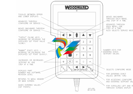
The programmer screen is a four-line, backlit LCD display. The display permits
you to look at two separate functions or menu items at the same time. Use the
UP/DOWN ARROW key to toggle between the two displayed items. The BKSP
and SPACE keys will scroll through the display to show the remainder of a
prompt if it is longer than the display screen's 18 characters.
The 723PLUS has two sets of menus—the Service menus and the Configure
menus. The Service menus allow easy access and tuning while the engine is
running. The Configure menus may be entered only if the I/O is shutdown (hence
the engine stopped).
Configure Menus
To access the Configure menus, the engine must be shut down. Press the key.
The display will show, “To select configure, press enter”. Press the ENTER key
and the display will show, “To shutdown I/O, press enter”. Press the ENTER key
and this will allow you into the Configure menus.
To move between the menus use the LEFT ARROW and RIGHT ARROW keys.
To move through the set points within a menu, use the UP ARROW and DOWN
ARROW keys. Once within a menu, to return to the menu header, press the ESC
key.
To leave the Configure menus press the ESC key. The set points will be
automatically saved when leaving Configure.
Service Menus
To access the Service menus press the DOWN ARROW key. To move between
menus, and to move through set points within menus follow the instructions as
for the Configure menus. Also to return to return to the menu header, or to leave
Service, follow the Configure instructions.
Adjusting Set Points
To adjust a set point, use the TURTLE UP or the RABBIT UP keys to increase
the value, and the TURTLE or RABBIT DOWN keys to decrease the value. The
RABBIT UP and RABBIT DOWN keys will make the rate of change faster than
the TURTLE UP and TURTLE DOWN keys. This is useful during initial setup
where a value may need to be changed significantly. Where necessary, to select
TRUE, use either the TURTLE UP or the RABBIT UP keys, and to select FALSE,
use the TURTLE DOWN or RABBIT DOWN keys.
Use the + or – keys to change integer values in the application software.
To obtain an exact value, press the = key. Key in the required figure and press
ENTER.
view the variables for your 723PLUS control on a PC (personal computer). These
instructions are meant to be introductory only. Full on-line help is available in
each application. It is assumed that you already have Servlink and Watch
Window installed. The default installation location can be found by clicking the
START icon (Microsoft Windows 95 or later) on the main menu bar and then
clicking the PROGRAMS menu item. Look for an icon called WOODWARD
WATCH WINDOW.
Make sure that all other programs that may access your computer
communications port are shut down.
Get the right cable to talk from your PC to the control (5416-614 will work for
J2 and J3. 5416-870 for J1).
Start the Servlink server and open a new file. Select the proper COM port for
your PC, verify that POINT TO POINT communications mode is selected,
and verify that the baud rate matches the baud rate of the 723PLUS. The
default baud rate is 19 200. See the on-line help file if you have been
changing the port settings of your control.
Select OK. If everything is working right, you should see an animated picture
of a string of “1”s and “0”s flying from the control to the PC on your screen.
You now have a network definition file whose default name is NET1. You
should save this file as “your filename.NET” (use FILE/SAVE AS). Link this
name to your control part number, as it will work only with that application.
For instance, if the upper level control number is 9907-031. you could save
the file as 9907031.NET. DO NOT DISCONNECT THE SERVER.
In the Servlink window you will now have another dialog window titled “your
filename.net”. In this window you will see a ballhead icon and a control
identifier name. Unless you have given the control a serial number (or name)
with the SLSN.EXE program, this name will display as “”.
Start the Watch Window application. When Watch Window executes, you will
have a screen displaying three windows entitled Watch Window, Explorer,
and Inspector.
The Explorer window will have two groups displayed, SERVICE and
CONFIGURE. Double clicking on either of these will expand them to show
groups of values. Explorer is used only to locate a tunable or monitor value.
In order to change a value or monitor a value, you must drag and drop a
value from the Explorer window into the Inspector window.
Once a value is displayed in the Inspector, you can see several blocks of
information. The most important blocks for a tunable value are the FIELD and
VALUE blocks. The FIELD block is used to identify a particular value, and the
VALUE block displays the current value of a variable. There are two types of
values available in Watch Window. One is a monitor value, which is marked
in the INSPECTOR window with a pair of glasses. This means it may only be
looked at. The other value is a read/write value, which is marked with a
pencil. The read/write type may be modified using the up and down arrows in
the value block.
Downloading to the 723PLUS
NOTE that this is the only way to download to a 723PLUS, and it will not work on
a regular 723.
Make sure that all other programs that may access your computer’s
communication port are shut down.
Get the right cable to talk from your PC to the control J1 port (5416-870).
Start the Servlink server and open a new file. From the dialog window, select
the proper COM port for your PC, select POINT TO POINT communications
mode, and set the baud rate to 19200.
Select OK. If everything is working right, you should see an animated picture
of a string of “1”s and “0”s flying from the control to the PC on your screen.
You now have a network definition file whose default name is NET1. You
should save this file. Link this name to your control part number as it will only
work with that application. For instance if the upper level control number is
9907-031. you could save the file as 9907031.NET. DO NOT DISCONNECT
THE SERVER.
In the Servlink window you will now have another dialog window titled “your
filename.net”. In this window you will see a ballhead icon and a control
identifier name. Unless you have given the control a serial number (or name)
with the SLSN.EXE program, this name will display as “”.
Start the Watch Window program. Under the title bar in the Explorer window
you will find a tab with your network file and the control ID displayed. Right
click this tab to display the pop-up menu, and select LOAD APPLICATION.
This will close the Inspector window and open a new window where you will
enter the name of the file you want to download. Once the filename is
correct, click on the OPEN button. A Warning screen will ask you to make
sure the engine is shut down before downloading. Downloading will proceed
automatically once your accept the message to shut down the engine.
Transferring Tunable Values Between 723PLUS
Controls
Note that this will not work with regular 723 controls.
Make sure that all other programs that may access your computer’s
communication port are shut down.
Get the right cable to talk from your PC to the control (5416-870 for J1. 5415-
614 for J2 or J3).
Start the Servlink server and open a new file. From the dialog window, select
the proper COM port for your PC, select POINT TO POINT communications
mode, and set the baud rate to 19200.
Select OK. If everything is working right, you should see an animated picture
of a string of “1”s and “0”s flying from the control to the PC on your screen.
You now have a network definition file whose default name is NET1. You
should save this file. Link this name to your control part number as it will only
work with that application. For instance if the upper level control number is
9907-031. you could save the file as 9907031.NET. DO NOT DISCONNECT
THE SERVER.
In the Servlink window you will now have another dialog window titled “your
filename.net”. In this window you will see a ballhead icon and a control
identifier name. Unless you have given the control a serial number (or name)
with the SLSN.EXE program, this name will display as “”.
Start the Watch Window program. Under the title bar in the Explorer window
you will find a tab with your network file and the control id displayed. Right
click this tab to display the pop-up menu, and select CONFIGURATION. If
you want to take the configuration from a control, select SAVE TO FILE. If
you want to download a new configuration to a control with an existing
application, then select LOAD FROM FILE.
If you select SAVE TO FILE, you will have to provide the name of a file
where you want to save the configuration. If your control has a part number
of 9907-031 then you might want to call this file 9907031.cfg. Make the name
meaningful so you can find it easily the next time you need it.
If you select LOAD FROM FILE you will get a confirmation warning telling
you that the unit will be shut down. If you answer yes then you will be asked
for the name of the configuration file that you want to download
-
HIRSCHMANN RS20-1600S2S2SDAEHH09.0.14 Ethernet switch
-
HIRSCHMANN MSM20-M2M2T1T1SY9HH9E99.9.99
-
HIRSCHMANN MSM20-M2M2M2M2SY9HH9E Ethernet media modul
-
HIRSCHMANN SPIDER-PL-20-05T1999999TWVHHHH Industrial Ethernet Rail Switch
-
Hirschmann SPIDER-PL-20-07T1M2M299TWVHHHH Industrial ETHERNET Rail Switch
-
Hirschmann (Belden) RS20-1600M2M2SDAEHC09.1.00 DIN-rail managed industrial Fast Ethernet switch
-
Hirschmann (Belden) RS30-1602O6O6TDAPHC09.1.00 DIN-rail managed industrial Ethernet switch
-
Hirschmann RS30-2402O6O6SDAP Ethernet switch
-
Hirschmann (Belden) RS30-2402O6T1SDAPHH09.0.13 DIN-rail industrial Ethernet switch
-
Hirschmann (Belden) RS30-2402O6T1SDAPHH09.0.13 DIN-rail industrial Ethernet switch
-
Hirschmann (Belden) SPIDER-PL-20-04T1S29999TY9HHHH Ethernet DIN-rail switch
-
HIRSCHMANN RS20-1600T1T1SDAUHX Switch
-
HIRSCHMANN BRS42-0012OOOO-SPCZ99HHSES industrial switch
-
Hirschmann RS20-0800S2S2TDHPHH09.0.14 Fast Ethernet DIN rail switch.
-
HIRSCHMANN MM20-Z6Z6M2M2SAHH Hybrid Fast Ethernet Media Module
-
HIRSCHMANN MM20-Z6Z6T1T1SAHH hot-swappable hybrid Fast Ethernet Media Module
-
HIRSCHMANN MM20-P9P9T1T1SAHH Hybrid Fast Ethernet Media Module
-
HIRSCHMANN MM20-M4T1T1T1SAHH Hybrid Fast Ethernet Media Module
-
HIRSCHMANN MM20-M4M4T1T1SAHH Hybrid Fast Ethernet Media Module
-
HIRSCHMANN MM20-M2M2M2M2SZHH Ethernet media module
-
HIRSCHMANN MM20-M2M2M2M2SAHH Ethernet media module
-
HIRSCHMANN MM20-T1T1T1T1EBH 4-port Fast Ethernet Copper Cable Media Module
-
HIRSCHMANN MM20-T1T1T1T1SAHH 4-port Fast Ethernet Copper Cable Media Module
-
HIRSCHMANN MM20-Z6Z6EBH Hot-swappable fast Ethernet media module
-
HIRSCHMANN MM20-Z6Z6SAHH Ethernet media module
-
HIRSCHMANN MM20-Z6Z6Z6Z6EBH Industrial Media Module
-
MSM40-T1T1T1TZ9HH9E99.9.99 HIRSCHMANN Switch
-
HIRSCHMANN MS20-0800SAAEHC / MS20-0800SAAEHC0 8-port modular Layer 2 management Ethernet switch
-
Hirschmann RSPM20-4T14T1SZ9HHS9 Switch RSPM20-4T14T1SZ9HHS9
-
HIRSCHMANN RS20-1600M2M2SDAEHH09.1. RS20/30/40 Managed Switch configurator
-
HIRSCHMANN RS20-1600M2M2SDAEHX09.0.00 Ethernet switch
-
HIRSCHMANN BELDEN SPIDER-PL-20-07T1M2M299TY9HHHH / SPIDERPL2007T1M2M299TY9HHHH
-
HIRSCHMANN MM3-1FXS2/3TX1 Switching Board Module
-
HIRSCHMANN RSPE30-24044O7T99-SCCV999HHSI2SXX.X.XX Switch
-
HIRSCHMANN RSPE30-24044O7T99-ECCP999HHSE2A08.1.00 Industrial-grade fanless management-type Ethernet switch
-
HIRSCHMANN RS30-1602OOZZSDAEHC09.1.00 DIN-rail-mounted managed Layer 2 Ethernet switch
-
HIRSCHMANN MACH104-20TX-F Managed 24-port Full Gigabit 19" Switch
-
HIRSCHMANN Switch RS20-0800M4M4SDAE
-
Hirschmann RS30-1602O6O6SDAEHH09.1. Management-type Ethernet switch
-
Hirschmann RS30-1602OOZZSDAEHC09.0.10 Open rack-style Ethernet switch
-
HIRSCHMANN RSPE30-24044O7T99-SCCV999HHSI2SXX.X.XX High-Availability Seamless Redundancy
-
HIRSCHMANN RSPE30-24044O7T99-SCCZ999HHSE2A DIN-rail Ethernet switch
-
HIRSCHMANN MM2-4TX1-EEC switch
-
HIRSCHMANN MSM40-T1T1T1T1TZ9HH9E99.9.99 Module
-
HIRSCHMANN RS20 Rail Switch RS20-0400S4T1SDAEHC07.1.01
-
HIRSCHMANN M4-FAST8-SFP Fast Ethernet media module
-
HIRSCHMANN RS20-0400M2T1SDAP Managed Fast-Ethernet-Switch
-
HIRSCHMANN BELDEN SPIDER II 8TX/1FX EEC Industrial Ethernet Rail Switch
-
HIRSCHMANN MM3-2FXS2/2TX1
-
HIRSCHMANN RS2-4TX/1FX EEC Industrial Ethernet Rail Switch 2
-
RS30-0802O6O6SDAEHC09.0.10 HIRSCHMANN Switch
-
HIRSCHMANN m4-8TP-RJ45 Ethernet Media Module
-
HIRSCHMANN MSP30-24040SCZ9URHHE3A switch
-
Hirschmann rack MS30-1602SAAPHC
-
HIRSCHMANN RS2-FX/FX Industrial Switch Module
-
Rs1txfx - Hirschmann - Rs1-Tx/Fx Rail Switch
-
RS20-0800S2S2SDAEHC09.1.00 HIRSCHMANN Commutator
-
Hirschmann EAGLE20 TX/TX Industrial Security Router
-
Hirschmann SPIDER-SL-20-04T1S29999SY9HHHH Industrial Switch
-
HIRSCHMANN MAR1040-4C4C4C4C9999SMMHRHHXX.X. Gigabit Ethernet Switch configurator
-
Hirschmann MAR1040 Industrial Switch
-
HIRSCHMANN BELDEN RS30-1602O6O6SDAE
-
Hirschmann RS20-1600M2M2SDAUHC Ethernet DIN rail switch
-
HIRSCHMANN OCTOPUS24M industrial switch
-
HIRSCHMANN RS20-1600T1T1SDAE Management-type Ethernet switch
-
HIRSCHMANN RS20-1600T1T1SDAUHH industrial switch
-
HIRSCHMANN RS20-0800M2M2SDAPHC09.0.04 switch
-
Hirschmann MR 8-03 24V DC Industrial Modular Bridge/Router
-
HIRSCHMANN RS20-0400M2T1SDAPHC08.0.01 Managed Switch
-
MACH1130 Hirschmann Industrial Switch
-
HIRSCHMANN 943824-002 SPIDER 5TX Industrial Ethernet Switch
-
HIRSCHMANN RS30-0802O6O6SDAEHC09.1.00 Managed Industrial Switch
-
HIRSCHMANN RS20-0400M2M2TDAEHC04.0.01 Industrial Switch
-
HIRSCHMANN BRS20-0600Z6Z6-STCZ99HHSES Industrial Switch
-
HIRSCHMANN MACH104-20TX-FR-L3P Industrial Ethernet Switch
-
HIRSCHMANN RS40-0009CCCCEDBPHH06.0.01 Industrial Switch
-
HIRSCHMANN RS2-3TX/2FX EEC Industrial Ethernet Switch
-
Hirschmann MACH 1020/1030 Fast/Gigabit Rack Mount Switches
-
HIRSCHMANN RS20-0800M2M2SDAPHC09.0.14 Industrial Switch
-
HIRSCHMANN RS20-1600T1T1SDAEHC09.0.04 Industrial Switch
-
HIRSCHMANN RSB20-0800T1T1EAABHH Industrial Switch
-
HIRSCHMANN MACH4002-48+4G-L3E Industrial Backbone Switch
-
HIRSCHMANN RS20-0400S2T1SDAE Industrial Managed Switch
-
HIRSCHMANN RS20-0800S2T1SDAUHC Industrial Switch
-
HIRSCHMANN RS20-2400S4S4SDAEHC09.0.14 industrial switch
-
HIRSCHMANN OS20-001200T5T5T5- TBBZ999HHNE3S 08.1.00 industrial switch
-
HIRSCHMANN RS40-0009CCCCSDAEHH09.0.14 switch
-
Hirschmann RS20-1600T1T1SDAUHC Management-type Ethernet Switch
-
Hirschmann M1-8SFP Switche
-
Hirschmann Industrial Ethernet Ruggedized Switch MACH1000 Family
-
Basler Electric, Solid State Protective Relay, BE1-60
-
BASLER ELECTRIC SR4A-2B15B3A Static Voltage Regulator
-
BASLER ELECTRIC EXCITER DIODE MONITOR EDM-200
-
BASLER ELECTRIC DECS125-15-B2C5 DIGITAL EXCITATION CONTROL SYSTEM V 2.0.9
-
BASLER ELECTRIC BE1-851 OVERCURRENT PROTECTION RELAY MECHANISM
-
BASLER ELECTRIC BE1-51/27CA1EZ10A0N0F / BE15127CA1EZ10A0N0F
-
BASLER ELECTRIC BE1-51/27CA1EZ10A0N0F / BE15127CA1EZ10A0N0F
-
BASLER ELECTRIC BE1-51A / BE151A
-
Basler Electric BE1-40Q Loss of Excitation Relay
-
Basler Electric BE1-87G Variable Percentage Differential Relay
-
Basler Electric BE1-11 Protection System I5A3M2P2N0EA00
-
BASLER ELECTRIC DECS-200-1C Digital Excitation Control System
-
Basler Electric / Kohler BE1-11g Generator Protection Relay G5A3M2J2N0E000
-
BASLER ELECTRIC DECS125-15 DIGITAL EXCITATION CONTROL SYSTEM
-
BASLER ELECTRIC BE1-951 OverCurrent Protecton System
-
Basler Electric DECS-200-1L Digital Excitation Control System
-
Basler Electric DGC-2020HD-5NS1DNSBA Digital Genset Controller
-
BASLER ELECTRIC BE1-81T1EE1WA0N1F / BE181T1EE1WA0N1F
-
BASLER ELECTRIC BE1-25M1EA6PN5R1F / BE125M1EA6PN5R1F
-
BASLER ELECTRIC DECS-250-LN1SN1N DIGITAL EXCITATION CONTROL SYSTEM
-
Basler Electric DECS-250-CN2CN 1N Digital Excitation Control System Unit
-
BASLER ELECTRIC DECS-300-C0N0 DIGITAL EXCITATION CONTROL SYSTEM
-
BASLER ELECTRIC BE1-87T-A1E-A1J-D0S1F / BE187TA1EA1JD0S1F
-
BASLER ELECTRIC BE1-11-G6D1M0J2P0E000 Protection System
-
BASLER ELECTRIC BE1-GPS100-E4N1H1N GENERATOR PROTECTION SYSTEM
-
Jaquet Relay card (Auxiliary module) FTV3090 377Z-03985
-
Jaquet Trip Chain Control card FTBU 3034 377Z-05030
-
Jaquet with input card -E04 FTFU 3024 -E04 377Z-05855
-
Jaquet with input card -E03 FTFU 3024- E03 377Z-03983
-
Jaquet FTFU 3024- E02 377Z-03982 with input card -E02
-
Jaquet FTFU 3024-E01 377Z-03981 with input card -E01
-
Hirschmann RS20-2400T1T1SDAE Industrial Managed Ethernet Switch
-
Hirschmann BELDEN EAGLE30-04022O6TT999SCCV9HSE3F
-
Hirschmann MM3-2FXS2/2TX MICE Media Module
-
Hirschmann RS20-1600M2M2SDAPHC08.0.05 Industrial Managed Switch
-
Hirschmann OZD Profi 12M G12-1300 PRO Fieldbus Repeater
-
Hirschmann SPIDER 4TX/1FX-ST EEC Industrial Ethernet Switch
-
Hirschmann MM2-2FXM3/2TX1 MICE Media Module
Add: High-tech Software Park, Xiamen City, Fujian Province
Mobile: +86-17750019513(WhatsApp)
Email: yy4291644@gmail.com
Website: https://www.abb-sis.com
.jpg)
.jpg)
.jpg)
.jpg)
.jpg)
.jpg)

-
HIRSCHMANN RS20-1600S2S2SDAEHH09.0.14 Ethernet switch
-
HIRSCHMANN MSM20-M2M2T1T1SY9HH9E99.9.99
-
HIRSCHMANN MSM20-M2M2M2M2SY9HH9E Ethernet media modul
-
HIRSCHMANN SPIDER-PL-20-05T1999999TWVHHHH Industrial Ethernet Rail Switch
-
Hirschmann SPIDER-PL-20-07T1M2M299TWVHHHH Industrial ETHERNET Rail Switch
