

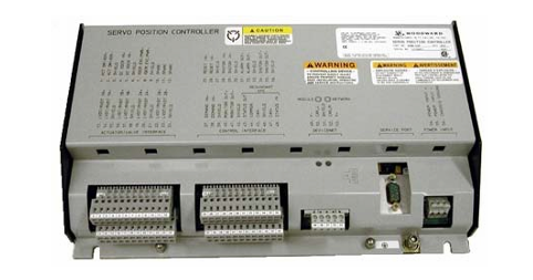
Woodward 505 Digital Controller For steam turbineses
8200-1300. 8200-1301. 8200-1302
The setting, or process control mode, depends on the configuration and system conditions.
The load distribution mode of EGCP-3 LS is used to distribute loads to those using EGCP-3 LS and tied to the same isolation busbar
Any other units of the line. When connected in parallel to the power grid, this mode is used together with EGCP-3 MC to allow
The EGCP-3 MC controls the frequency or load of the power plant depending on its operating status.
The remote load setting mode of EGCP-3 LS allows a remote 4-20 mA signal to set the load. EGCP
The process control mode of 3LS allows for the control of any process directly related to the generator load.
After synchronization, it can be obtained by EGCP-3 LS (via 505 synchronization/load input) or by the internal speed of 505 /
The load setting value controls the load of the unit. When configuring the synchronous/load input, the position of the contacts of the power grid circuit breaker is open
Select the unit load control through the internal load setting values of EGCP-3 LS or 505.
Once the generator is synchronized with the EGCP-3 LS software load, the unit to the load setting has an operating mode (base load,
Load distribution and process control have been determined. Upon receiving the instruction, EGCP-3 LS can also perform software unloading on the unit
Negative, simultaneously issue a circuit breaker disconnection command at a set power level.
The PowerSense board receives PT and CT inputs for the generator and busbar to be used within the system controller
The parameters were calculated using EGCP-3. The algorithm used is based on IEEE 1459-2000. For the generator and busbar
The following parameters are provided: Hz, Vac, Amps, W, VA, VAR, PF, phase, voltage modulation, and electricity
Current regulation, negative phase sequence voltage, negative phase sequence current. In the 4-20mA analog output, optional: synchronous oscilloscope,
Generator measurement, main line measurement.
EGCP-3 LS is equipped with the following busbar protection:
Overvoltage/undervoltage (59.27)
Overfrequency/underfrequency (81O, 81U)
Directional (forward/reverse) power (32) *
Negative sequence overcurrent (46
Negative sequence overvoltage (47
Phase overcurrent (51) *
Voltage limiting phase overcurrent (51V) *
Directional VAR
Phase current imbalance (46
The EGCP-3 LS is equipped with the following generator protections:
Overvoltage/undervoltage (59.27)
Overfrequency/underfrequency (81O, 81U)
Directional (input/output) power (32) *
Negative sequence overcurrent (46
Negative sequence overvoltage (47
Phase overcurrent (51) *
Directional VAR
Phase current imbalance (46) *
The rotational speed/frequency is mismatched
Apply 505 in conjunction with redundant I/H or I/P converters
505 can be applied in simplex or redundant actuator systems. For redundant actuator applications, actuators
Channel 1 is configured to lead for HP instructions, and Channel 2 is configured for zero-bias HP2 requirements. this
It will provide the full current from the two actuator drive circuits to the driven device
The selection between the output signals of the converter can be accomplished by using an edge valve or a solenoid delivery valve. Converter status (I/H
Or I/P and pressure feedback signals can be selectively configured into the 505. If necessary, the relay output can be configured
Switch between the outputs of the converter. Manual switching between converters can be achieved through discrete input and Modbus
Or use the PC interface command to start. The automatic switching between converters is carried out by 505 based on drive failure and conversion
The feedback signals of the device status, the output pressure of the converter and the input pressure of the servo mechanism are provided.
Functional details
The use of a dual-actuator configuration can provide redundancy up to the actuator level. A typical redundant I/H (or I/P) system
The milliampere output of the 505 actuator will be converted into the corresponding hydraulic (or pneumatic) pressure of the positioning servo mechanism cylinder
Force. Both converters supply the appropriate pressure to position the steam valve as required by the controller. One of the conversions
One will control the valve position requirements, while the other will be in standby mode. The selection between the output signals of the converter can be made using edges
It can be accomplished by using a valve or a solenoid conveyor valve. The edge valve will select the higher pressure output of the two converters, the solenoid transfer valve
Then select the output of one converter and switch between the two converters based on the relay command from the 505 controller
Change. Either type of valve can be used. Refer to the conveyor valve section for the respective advantages of the two types of valves
Information on strengths/weaknesses.
The converter status (I/H or I/P) and pressure feedback signals should be configured into 505 because of the automatic between converters
Switching is provided and handled by the states of these signals. If necessary, a relay output can be configured (configuration)
It is a relay that serves a control function to switch between the outputs of the converter.
-
CTI 2599 8/16/32-Point AC Output Module
-
CTI 2598-8 8-Point AC Output Module
-
CTI 2598 8/16-Point AC Output Module
-
CTI 2597 8/16/32-Point DC Output Module
-
CTI 2596-8 8-Point DC Output Module
-
CTI 2596 8/16-Point DC Output Module
-
CTI 2595 16-Point TTL/Word Output Module
-
CTI 2591-EF 16-Point Isolated 11-146 VDC Output with Front Panel Accessible Fuses
-
CTI 2591-A 16-Point Isolated 11-146 VDC Output Module
-
CTI 2590-EF 16-Point Isolated 20-132 VAC Output with Front Panel Accessible Fuses
-
CTI 2590-A 16-Point Isolated Discrete 20-132 VAC Output Module
-
CTI 2589-B 8/16/32-Point Universal Discrete Input Module
-
CTI 2589-A 8/16/32-Point Universal Discrete Input Module
-
CTI 2588-8 8-Point Universal Discrete Input Module
-
CTI 2585 16-Point TTL/Word Input Module
-
CTI 2582 16-Point Isolated 125 VDC Input Module
-
CTI 2581 16-Point Isolated 12-56 VDC Input Module
-
CTI 2580 16-Point Isolated 95-132 VAC Input Module
-
CTI 2500-TAP RS485 Network Tap
-
CTI 2500-RIO-B RS485 Remote Base Controller
-
CTI 2500-RIO-A RS485 Remote Base Controller
-
CTI 2500-RBC Profibus Remote Base Controller
-
CTI 2515-A 100-Watt AC/DC Power Supply with Redundancy Support
-
CTI 2515 100-Watt AC Power Supply (MATURE - replaced by 2515-A)
-
CTI 2513-A 75-Watt DC Power Supply with Redundancy Support
-
CTI 2513 75-Watt 24VDC Power Supply
-
CTI 2512-A 75-Watt AC/DC Power Supply with Redundancy Support
-
CTI 2512 75-Watt AC/DC Power Supply
-
CTI 2510 125 VDC Power Supply
-
CTI 2500-SSB Single Slot Blank Front Panel
-
CTI 2500-R11-A Eleven-Slot Redundant Base
-
CTI 2500P-R16 Sixteen-Slot Base with High-Speed Channel
-
CTI 2500P-R8 Eight-Slot Base with High-Speed Channel
-
CTI 2500P-R4 Four-Slot Base with High-Speed Channel
-
CTI 2541 Redundant Processor Manager Module
-
CTI 2577 Profibus DP Slave Adapter
-
CTI 2573-MOD Serial Interface Adapter with MODBUS
-
CTI 2572-AF Fast Ethernet TCP/IP Adapter with Optical Fiber Connection
-
CTI 2572-A Fast Ethernet TCP/IP Adapter
-
CTI 2572 Ethernet TCP/IP Adapter
-
CTI 2572-B Fast Ethernet TCP/IP Adapter
-
CTI 2576 DeviceNet™ Scanner Module (MATURE)
-
CTI 2500P-ECC1 Ethernet Communications Coprocessor
-
CTI 2500P-JACP Janus Application Coprocessor
-
CTI 2500P-ACP1 Application Coprocessor (MATURE - replaced by 2500P-JACP)
-
CTI 2500P-J450 Janus PAC with 2MB Project Memory
-
CTI 2500-C400 CPU with 3072K User Memory
-
CTI 2500-C300 CPU with 512K User Memory
-
CTI 2500-C200 CPU with 256K User Memory
-
CTI 2500-C100 CPU with 128K User Memory
-
CTI 2500P-J750 Janus PAC with 3MB Project Memory
-
Shinkawa WHF3006M Displacement Converter
-
Shinkawa JBP-220 (P-24-94A / P-24-94B) Circuit Board Module
-
SHINKAWA WKN-142K5 2-WIRE VIBRATION TRANSDUCER
-
Shinkawa FRP-321 (P-26-54A / P-26-54B) Circuit Board Module
-
Shinkawa IOP-160 (P-25-72A / P-25-72B) Circuit Board Module
-
Shinkawa PK-147B-1 / PK-147A-1 Circuit Board Module
-
Shinkawa CPP-91A Circuit Board Module
-
Shinkawa FRP-177 PCB Module
-
Shinkawa CPP-127 (P-26-74A / P-26-74B) Circuit Board Module
-
Shinkawa FRP-227 (P-24-86A / P-24-86B) Circuit Board Module
-
Shinkawa MDP-104 (P-25-83A / P-25-83B) Circuit Board Controller
-
Shinkawa VK-143P2 High-precision eddy current sensor driver/signal conditioner
-
Shinkawa FRP-226 (P-24-86A / P-24-86B) Circuit Board Module
-
Shinkawa CPP-107A P-22-99A P-22-99B Circuit Board Module
-
SHINKAWA VW-202AL-8 Axial Displacement Sensor
-
Shinkawa VL-202A08L-1A42 Vibration Sensor Transducer Probe
-
Shinkawa FRP-209A & FRP-206 Wire Bonder Circuit Board Module
-
Shinkawa MGP-72 MGP72 P-26-50A P-26-50B Circuit Board Module
-
Shinkawa FRP-249 P-25-1A P-25-1B Circuit Board Module
-
Shinkawa FRP-320 P-26-54A P-26-54B Circuit Board Module
-
Shinkawa FRP-282 P-24-35A P-24-35B Circuit Board Module
-
Shinkawa FRP-338 P-26-54A P-26-54B Circuit Board Module
-
GE IS200AEPBH1B Pitch-Charger Control PCB Board
-
GE IS200EDEXG1ADA EX2100 SCR Trigger Control Board
-
GE 151X1207CK01SA01 IS200EDEXG1A EX2100 SCR
-
GE 151X1233DD02SA02 IS200AEPBH1B - Variant for pitch control charger assembly
-
GE 151X1233DB01SA01 IS200AEPBH1B - 10kW Wind Power Converter
-
GE 151X1233DB01SA01 IS200AEPBH1B - 10kW Wind Power Converter
-
GE 151X1233DB01SA01R | IS200AEPBH1B 10KW Converter
-
GE 151X1233DD01SA02 Pitch Battery Charger (109W6931P001)
-
GE 151X1233DD01SA02 Pitch Battery Charger Assy IS200AEPBH1B
-
GE 151X1233DB02SA02 Rev A IS200AEPBH1B Wind Turbine Converter
-
GE 151X1207CK02SA02 SCR 4400 V 1850 A IS200EDEXG1ADA General Electric EX2100
-
Triconex 3723X 32-Channel TMR Analog Input Module with HART
-
SHINKAWA VM-21G SIGNAL CONDITIONER SOCKET
-
SHINKAWA VM-21R REVOLUTION SIGNAL CONDITIONER
-
SHINKAWA VM-21T DISPLACEMENT INPUT THRUST SIGNAL CONDITIONER
-
SHINKAWA VM-21D 6-WIRE LVDT SIGNAL CONDITIONER
-
SHINKAWA VM-21P 3-WIRE LVDT SIGNAL CONDITIONER
-
SHINKAWA VM-21A VIBRATION SIGNAL CONDITIONER
-
SHINKAWA VM-21K DISPLACEMENT INPUT VIBRATION SIGNAL CONDITIONER
-
SHINKAWA VM-25S01 CONDITION MONITORING SYSTEM
-
SHINKAWA VM-25 CONDITION MONITORING SYSTEM
-
SHINKAWA VM-772B DEVICE CONFIG
-
SHINKAWA VM-771B MCL VIEW
-
SHINKAWA VM-76B INSTRUMENT RACK
-
SHINKAWA VM-75B POWER SUPPLY MODULE
-
SHINKAWA VM-742B NETWORK COMMUNICATION MODULE
-
SHINKAWA VM-741B LOCAL COMMUNICATION & PHASE MARKER MODULE
-
SHINKAWA VM-722B 9-CHANNEL RELAY MODULE
-
SHINKAWA VM-707B AERODERIVATIVE GAS TURBINE MONITOR MODULE
-
SHINKAWA VM-706B ROD DROP MONITOR MODULE
-
SHINKAWA VM-705B 18-CHANNEL TEMPERATURE MONITOR MODULE
-
SHINKAWA VM-704B TEMPERATURE MONITOR MODULE
-
SHINKAWA VM-703B TACHOMETER & ECCENTRICITY MONITOR MODULE
-
SHINKAWA VM-702B ABSOLUTE VIBRATION MONITOR MODULE
-
SHINKAWA VM-701B VIBRATION / DISPLACEMENT MONITOR MODULE
-
SHINKAWA MODEL VM-5X INTERFACE UNIT
-
SHINKAWA MODEL VM-5W2 DUAL POWER SUPPLY INSTRUMENT RACK
-
SHINKAWA MODEL VM-5H4 INSTRUMENT RACK (for VM-5Z5.6.7)
-
SHINKAWA MODEL VM-5G SINGLE UNIT INSTRUMENT RACK
-
SHINKAWA MODEL VM-5Z5,6,7 POWER SUPPLY UNIT
-
SHINKAWA MODEL VM-5Y1,2,3 RELAY MODULE UNIT
-
SHINKAWA MODEL VM-5P3 PHASE MARKER UNIT
-
SHINKAWA MODEL VM-53 DUAL COMMUNICATION UNIT
-
SHINKAWA MODEL VM-52 BOTTOM HOLD MONITOR
-
SHINKAWA MODEL VM-51 ROD DROP MONITOR
-
SHINKAWA MODEL VM-5R TACHOMETER
-
SHINKAWA MODEL VM-5S DUAL TACHOMETER
-
SHINKAWA MODEL VM-5A DUAL VALVE
-
SHINKAWA MODEL VM-5E DUAL CASE
-
SHINKAWA MODEL VM-5L COMPLEMENTARY INPUT
-
SHINKAWA MODEL VM-5N RAMP DIFFERENTIAL
-
SHINKAWA MODEL VM-5D DUAL DIFFERENTIAL
-
SHINKAWA MODEL VM-5T DUAL THRUST MONITOR
-
SHINKAWA MODEL VM-5C ECCENTRICITY MONITOR
-
SHINKAWA MODEL VM-5C ECCENTRICITY MONITOR

Add: High-tech Software Park, Xiamen City, Fujian Province
Mobile: +86-17750019513(WhatsApp)
Email: yy4291644@gmail.com
Website: https://www.abb-sis.com
.jpg)
.jpg)
.jpg)
.jpg)
.jpg)
.jpg)

-
CTI 2599 8/16/32-Point AC Output Module
-
CTI 2598-8 8-Point AC Output Module
-
CTI 2598 8/16-Point AC Output Module
-
CTI 2597 8/16/32-Point DC Output Module
-
CTI 2596-8 8-Point DC Output Module
