

alstom AMS42/84 5B Amplifier SystemAmplifier Technology at its Best.
(see fig. above) must be closed.
In the case of electrically connected systems (e.g. PC), this jumper represents a high-resistance
bridge (1k ) and may generate a hum loop!
3.2 Module Pin Assignment
The pin assignment on the right shows the top view of the module
backplane (see chapter 3).
The pin assignment corresponds to the 5B modules of Analog
Devices®, BURR BROWN® etc. However, an additional 0EX pin has
been introduced, which is particularly suitable for ungrounded
shielding. This is a specific assignment of BMC Messsysteme
GmbH. The 0EX pin is not connected in modules of other
manufacturers.
3.3 Fuse
The fusing of the AMS backplane is effected on the backplane (see chapter 3) with one reversible
semi-conductor fuse. In case of overload, it turns off. To make the fuse work effectively again, first
remove the cause for overload before disconnecting the power supply of the AMS42/84.
3.4 Connection for AMS Cassettes
The cassettes are connected to the AMS backplane via 7-way pin connectors,
leading the input signals connected at the cassette panel to the backplane. The
assignment of the 7-way female connector on the board is illustrated in the figure on
the right-hand side.
4 Supplementary Products for AMS42/84
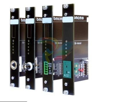
4.1 5B Modules (MA Line)
The 5B measuring amplifiers from bmcm allow for the professional
signal adjustment to a data acquisition system.
The amplifier output is 5V or 0..5V. Most of the modules are
electrically isolating and provide sensor supply.
The following 5B modules from bmcm are available:
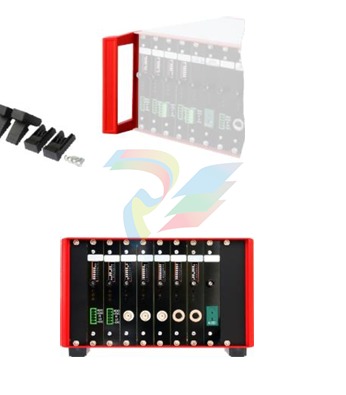
4.2 Plug-in Cassettes (AMS-K Line)
The amplifier system can be individually equipped with 8
(AMS42-USB) or 16 (AMS84) plug-in cassettes.
Each cassette is equipped with the relevant 5B module and
suitable input connector.
The suitable input connector on the front panel guarantees for
the relevant connection to be available when exchanging the
cassette.
The following cassettes are available:
Product
Description
AMS-K-BIN5
cassette with panel and 5-pin Binder female connector (712 series)
AMS-K-BLANK blank panel
AMS-K-BNC
AMS-K-CO5
cassette with front panel and BNC female connector
cassette with front panel and 5-pin terminal connector
AMS-K-THK
cassette with front panel and thermocouple socket (type K)
4.3 AMS-HANDLE2. AMS-FOOT
For mobile use, the AMS42/84 can be equipped with two stable
metal handles at the housing frame (AMS-HANDLE2).
If the AMS84 is not installed in a 19'' rack, a set of tip-up feet
(AMS-FOOT) can optionally be ordered.
4.4 AMS-EXT8
With the add-on option AMS-EXT8. 8 additional analog channels are
available at the back of the AMS42. In this case the device features max. 16
channels.
The analog outputs are accessible at a second D-Sub37 female with the
same assignment as the standard D-Sub37 female of the AMS device (see
chapter 2.3).
5 Important Notes for Using the AMS42/84
AMS42/84
• The device is only suitable for extra-low voltages - please observe the relevant regulations! For reasons
relating to EMC, it must only be used in closed PC housings.
• Only use an electrical isolated power supply unit (with CE).
• Only use non-solvent detergents for cleaning. The product is designed to be maintenance-free.
• For calibration purposes, the device must be returned to BMC Messsysteme GmbH.
• Use shielded cables for reasons relating to CE. Connect the shield to ground at one end only. Close open
inputs if possible.
• When mounting the cassettes, a connection between power supply ground and chassis of the device is made
via the module screw.
• The device must not be used for safety-relevant tasks. With the use of the product, the customer becomes
manufacturer by law and is therefore fully responsible for the proper installation and use of the product. In the
case of improper use and/or unauthorized interference, our warranty ceases and any warranty claim is
excluded.
-
Shinkawa WHF3006M Displacement Converter
-
Shinkawa JBP-220 (P-24-94A / P-24-94B) Circuit Board Module
-
SHINKAWA WKN-142K5 2-WIRE VIBRATION TRANSDUCER
-
Shinkawa FRP-321 (P-26-54A / P-26-54B) Circuit Board Module
-
Shinkawa IOP-160 (P-25-72A / P-25-72B) Circuit Board Module
-
Shinkawa PK-147B-1 / PK-147A-1 Circuit Board Module
-
Shinkawa CPP-91A Circuit Board Module
-
Shinkawa FRP-177 PCB Module
-
Shinkawa CPP-127 (P-26-74A / P-26-74B) Circuit Board Module
-
Shinkawa FRP-227 (P-24-86A / P-24-86B) Circuit Board Module
-
Shinkawa MDP-104 (P-25-83A / P-25-83B) Circuit Board Controller
-
Shinkawa VK-143P2 High-precision eddy current sensor driver/signal conditioner
-
Shinkawa FRP-226 (P-24-86A / P-24-86B) Circuit Board Module
-
Shinkawa CPP-107A P-22-99A P-22-99B Circuit Board Module
-
SHINKAWA VW-202AL-8 Axial Displacement Sensor
-
Shinkawa VL-202A08L-1A42 Vibration Sensor Transducer Probe
-
Shinkawa FRP-209A & FRP-206 Wire Bonder Circuit Board Module
-
Shinkawa MGP-72 MGP72 P-26-50A P-26-50B Circuit Board Module
-
Shinkawa FRP-249 P-25-1A P-25-1B Circuit Board Module
-
Shinkawa FRP-320 P-26-54A P-26-54B Circuit Board Module
-
Shinkawa FRP-282 P-24-35A P-24-35B Circuit Board Module
-
Shinkawa FRP-338 P-26-54A P-26-54B Circuit Board Module
-
GE IS200AEPBH1B Pitch-Charger Control PCB Board
-
GE IS200EDEXG1ADA EX2100 SCR Trigger Control Board
-
GE 151X1207CK01SA01 IS200EDEXG1A EX2100 SCR
-
GE 151X1233DD02SA02 IS200AEPBH1B - Variant for pitch control charger assembly
-
GE 151X1233DB01SA01 IS200AEPBH1B - 10kW Wind Power Converter
-
GE 151X1233DB01SA01 IS200AEPBH1B - 10kW Wind Power Converter
-
GE 151X1233DB01SA01R | IS200AEPBH1B 10KW Converter
-
GE 151X1233DD01SA02 Pitch Battery Charger (109W6931P001)
-
GE 151X1233DD01SA02 Pitch Battery Charger Assy IS200AEPBH1B
-
GE 151X1233DB02SA02 Rev A IS200AEPBH1B Wind Turbine Converter
-
GE 151X1207CK02SA02 SCR 4400 V 1850 A IS200EDEXG1ADA General Electric EX2100
-
Triconex 3723X 32-Channel TMR Analog Input Module with HART
-
SHINKAWA VM-21G SIGNAL CONDITIONER SOCKET
-
SHINKAWA VM-21R REVOLUTION SIGNAL CONDITIONER
-
SHINKAWA VM-21T DISPLACEMENT INPUT THRUST SIGNAL CONDITIONER
-
SHINKAWA VM-21D 6-WIRE LVDT SIGNAL CONDITIONER
-
SHINKAWA VM-21P 3-WIRE LVDT SIGNAL CONDITIONER
-
SHINKAWA VM-21A VIBRATION SIGNAL CONDITIONER
-
SHINKAWA VM-21K DISPLACEMENT INPUT VIBRATION SIGNAL CONDITIONER
-
SHINKAWA VM-25S01 CONDITION MONITORING SYSTEM
-
SHINKAWA VM-25 CONDITION MONITORING SYSTEM
-
SHINKAWA VM-772B DEVICE CONFIG
-
SHINKAWA VM-771B MCL VIEW
-
SHINKAWA VM-76B INSTRUMENT RACK
-
SHINKAWA VM-75B POWER SUPPLY MODULE
-
SHINKAWA VM-742B NETWORK COMMUNICATION MODULE
-
SHINKAWA VM-741B LOCAL COMMUNICATION & PHASE MARKER MODULE
-
SHINKAWA VM-722B 9-CHANNEL RELAY MODULE
-
SHINKAWA VM-707B AERODERIVATIVE GAS TURBINE MONITOR MODULE
-
SHINKAWA VM-706B ROD DROP MONITOR MODULE
-
SHINKAWA VM-705B 18-CHANNEL TEMPERATURE MONITOR MODULE
-
SHINKAWA VM-704B TEMPERATURE MONITOR MODULE
-
SHINKAWA VM-703B TACHOMETER & ECCENTRICITY MONITOR MODULE
-
SHINKAWA VM-702B ABSOLUTE VIBRATION MONITOR MODULE
-
SHINKAWA VM-701B VIBRATION / DISPLACEMENT MONITOR MODULE
-
SHINKAWA MODEL VM-5X INTERFACE UNIT
-
SHINKAWA MODEL VM-5W2 DUAL POWER SUPPLY INSTRUMENT RACK
-
SHINKAWA MODEL VM-5H4 INSTRUMENT RACK (for VM-5Z5.6.7)
-
SHINKAWA MODEL VM-5G SINGLE UNIT INSTRUMENT RACK
-
SHINKAWA MODEL VM-5Z5,6,7 POWER SUPPLY UNIT
-
SHINKAWA MODEL VM-5Y1,2,3 RELAY MODULE UNIT
-
SHINKAWA MODEL VM-5P3 PHASE MARKER UNIT
-
SHINKAWA MODEL VM-53 DUAL COMMUNICATION UNIT
-
SHINKAWA MODEL VM-52 BOTTOM HOLD MONITOR
-
SHINKAWA MODEL VM-51 ROD DROP MONITOR
-
SHINKAWA MODEL VM-5R TACHOMETER
-
SHINKAWA MODEL VM-5S DUAL TACHOMETER
-
SHINKAWA MODEL VM-5A DUAL VALVE
-
SHINKAWA MODEL VM-5E DUAL CASE
-
SHINKAWA MODEL VM-5L COMPLEMENTARY INPUT
-
SHINKAWA MODEL VM-5N RAMP DIFFERENTIAL
-
SHINKAWA MODEL VM-5D DUAL DIFFERENTIAL
-
SHINKAWA MODEL VM-5T DUAL THRUST MONITOR
-
SHINKAWA MODEL VM-5C ECCENTRICITY MONITOR
-
SHINKAWA MODEL VM-5C ECCENTRICITY MONITOR
-
SHINKAWA MODEL VM-5M DUAL PATH MONITOR
-
SHINKAWA MODEL VM-5B DUAL ACCELERATION MONITOR
-
SHINKAWA MODEL VM-5B DUAL ACCELERATION MONITOR
-
SHINKAWA MODEL VM-5U DUAL SEISMIC MONITOR
-
SHINKAWA MODEL VM-55 VIBRATION MONITOR
-
SHINKAWA VM-742B1-5 VIBRATION MONITORING SYSTEM CARD
-
Shinkawa PSP-17B P-24-64A P-24-64B Circuit Board Module
-
SHINKAWA MGP-67 PCB
-
Shinkawa JBP-278 P-22-48A-1 P-22-48B-1 Circuit Board Module
-
Shinkawa VM-721B 18-CHANNEL RELAY MODULE
-
Shinkawa FRP-337 P-26-54A P-26-54B Circuit Board Module
-
Shinkawa WKN-142K2-2 Vibration Transmitter
-
SHINKAWA VL-202A08L-1012 Rotor Position Monitor Probe Sensor
-
Shinkawa CPP-128 P-26-74A P-26-74B Circuit Board Module
-
Honeywell 51402755-100 PROCESSOR CARD
-
Honeywell 51107595-100 Power
-
HONEYWELL 51304544-100 Control Board
-
HONEYWELL 51109919-100 BOARD
-
HHoneywell 51204160-175 Digital Input Module
-
Honeywell 51304754-150 High Level Analog Input Module
-
HONEYWELL 51304690-100 DIGITAL INPUT CARD
-
Honeywell 51401635-150 COMM CONTROL
-
HONEYWELL 51204174-175 MC-TAOY 52 ANALOG OUTPUT BOARD
-
HONEYWELL 51400596-100
-
HONEYWELL 51401291-100 board card
-
HONEYWELL 51401642-150 I/O LINK MODULE
-
Honeywell LCN‑E Hub Power Supply 38500148‑300
-
Honeywell LCN‑E Hub redundant 38500143‑202 Twisted‑pair LCN
-
Honeywell LCN‑E Hub non‑redundant,38500143‑102
-
Honeywell Enhanced Micro‑TDC‑3000 System Unit MX‑DTAC01K2
-
Honeywell Enhanced Micro‑TDC‑3000 System Unit MX‑DTAB01K2
-
Honeywell Enhanced Micro‑TDC‑3000 System Unit MT11‑520
-
Honeywell STI‑CE Smart Transmitter Interface 51304516‑150
-
Honeywell STI Smart Transmitter Interface 51304516‑100 MC‑PSTX02
-
Honeywell ulse Counter IOP 51304386‑100 MU‑PPIX02
-
Honeywell DO Digital Output IOP‑CE 51304487‑150 CE version
-
Honeywell DO Digital Output IOP 51304487‑100 MC‑PDOX02
-
Honeywell TDC‑3000 SOE DI IOP,51402625-175 MC‑PDIS12
-
Honeywell TDC‑3000 DI Digital Input IOP‑CE 51304485‑150
-
Honeywell TDC‑3000 DI Digital Input IOP 51304485‑100 MC‑PDIX02
-
Honeywell TDC‑3000 AO Analog Output IOP 51304757‑100 MU‑PAOX02
-
Honeywell TDC‑3000 TC Thermocouple IOP 51304756‑100 MU‑TAMT03
-
Honeywell TDC‑3000 51304755‑100 MU‑TAMR03
-
Honeywell TDC‑3000 LLAI Multiplex AI IOP,51304362‑150
-
Honeywell TDC‑3000 HLAI Analog Input IOP‑CE, 51304363‑150
-
Honeywell TDC‑3000 HLAI Analog Input IOP,51304363‑100.4‑20mA
-
Honeywell TDC‑3000 HPM Power Supply,51401731‑100
-
Honeywell TDC‑3000 Standard 1986.HPM High‑Performance PM CPU,51402362‑100
-
Honeywell TDC‑3000 APM Advanced Process Manager CPU,51304459‑100
-
Honeywell TDC‑3000 Standard 1986.PM Process Manager CPU,51304362‑100
-
Honeywell TDC‑3000 NIM Network Interface Module,51304481‑200

Add: High-tech Software Park, Xiamen City, Fujian Province
Mobile: +86-17750019513(WhatsApp)
Email: yy4291644@gmail.com
Website: https://www.abb-sis.com
.jpg)
.jpg)
.jpg)
.jpg)
.jpg)
.jpg)

-
Shinkawa WHF3006M Displacement Converter
-
Shinkawa JBP-220 (P-24-94A / P-24-94B) Circuit Board Module
-
SHINKAWA WKN-142K5 2-WIRE VIBRATION TRANSDUCER
-
Shinkawa FRP-321 (P-26-54A / P-26-54B) Circuit Board Module
-
Shinkawa IOP-160 (P-25-72A / P-25-72B) Circuit Board Module
