


- Beckhoff
- UNIOP
- Sieger
- Autronica
- SAMSUNG
- Stucke Elektronik
- Moore
- NI
- EMERSON
- IBA
- SST
- LEYBELOD
- SAMSUNG
- METSO
- AMAT
- Phoenix
- LAND
- LAMBDA
- Abaco
- Kongsberg
- ALFA LAVAL
- Pacific Scientific
- Others
- OMRON
- AMAT
- ICS Triplex
- Lam Research
- KUKA
- Hirschmann
- ELAU
- EATON
- Applicom
- Watlow Anafaze
- Meggitt Vibro-meter
- Carrier
- Other
- ROCKWELL
- Rolls-Royce
- SAACKE
- Yokogawa
- B&R
- Reliance Electric
- Seifert
- A-B
- Weimeide Metso
- KEBA
- HIMatrix
- Valmet
- Schneider
- Prosoft
- PEPPERL+FUCHS
- Honeywell
- Woodward
- GE
- GEA Westfalia Separator
- Bently Nevada
- ALSTOM
- Foxboro
- MOTOROLA
- Fanuc
- VMIC
- KOLLMORGEN
- SEW
- Rexroth
- AEROTECH
- TOSHIBA
- TmeIC
- Sumitomo
- SOCAPEL SOCASIN
- SMC
- Stromag
- SIEMENS
- SCHUMACHER
- ABB
- MOOG
- EPRO
- EMERSON
- Triconex
ABB PFCL201CE 50KN 3BSX802939-108 sensor
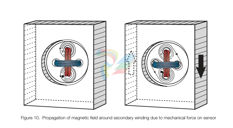
Measuring principle of the sensor
The measuring principle of the sensor is based on the Pressductor® technology and the fact that the permeability of a magnetic material changes under mechanical stress.
The sensor is a membrane machined in the load cell. Primary and secondary windings are wound through four holes in the load cell so that they cross at right angles.
The primary winding is supplied with an alternating current which creates a magnetic field around the primary winding. Since the two windings are at right angles to each other, there will be no mag netic field around the secondary winding, as long as there is no load on the sensor.
When the sensor is subjected to a mechanical force in the direction of measurement, the propaga tion of the magnetic field changes so that it surrounds the secondary winding, inducing an alternat ing voltage in that winding.
The control unit converts this alternating voltage into a DC voltage proportional to the applied force. If the measurement force changes direction, the sensor signal changes also polarity.
Mounting Arrangement
When choosing a mounting arrangement it is important to remember to position the load cell in a
direction that gives sufficient measuring force (FR) to achieve the highest possible accuracy.
The load cell has no particular correct orientation; it is positioned in the orientation best suited for
the application, bearing in mind the positions of the screw holes. The load cell can also be installed
with the roll suspended under the load cell.
The load cell has the same sensitivity in both tension and compression, so the load cell can be
installed in the easiest manner.
Typical mounting arrangements are horizontal and inclined mounting.
Coordinate System
A coordinate system is defined for the load cell. This is used in force calculations to derive force
components in the load cell principal directions.
Where direction designations R, V and A are recognized as suffixes for force components, F, this represents the force component in the respective direction. The suffix R may be omitted, when measuring direction is implied by the context.
Horizontal Mounting In the majority of cases horizontal mounting is the most obvious and simplest solution. Stand, mounting surface and shims (if required) are simple and cheap to make. When calculating the force, the equations below must be used: FR = T × (sin α + sin β) FRT = Tare FRtot = FR + FRT = T × (sin α + sin β) + Tare FV = T × (cos β - cos α) FVT = 0 FVtot = FV + FVT = T × (cos β - cos α) + 0 = T × (cos β - cos α) where: T = Strip tension FR = Force component from strip tension in measurement direction, R FRT = Force component from Tare in measurement direction, R FRtot = Total force in measurement direction, R FV = Force component from strip tension in transverse direction, V FVT = Force component from Tare in transverse direction, V FVtot = Total force in transverse direction, V Tare = Force due to tare weight α = Deflection angle on one side of the roll relative the horizontal plane β = Deflection angle on the other side of the roll relative the horizontal plane
Inclined Mounting
Inclined mounting means arrangements in which the load cell is inclined relative to the horizontal
plane. In some cases this is the only option.
When calculating the force, the equations below must be used:
FR = T × [sin (α - γ) + sin (β + γ)] FRT = Tare × cos γ FRtot = FR + FRT = T × [sin (α - γ) + sin (β + γ)] + Tare × cos γ FV = T × [cos (β + γ) - cos (α - γ)] FVT = - Tare × sin γ FVtot = FV + FVT = T × [cos (β + γ) - cos (α - γ)] - Tare × sin γ γ = 90° - φ where: T = Strip tension FR = Force component from strip tension in measurement direction, R FRT = Force component from Tare in measurement direction, R FRtot = Total force in measurement direction, R FV = Force component from strip tension in transverse direction, V FVT = Force component from Tare in transverse direction, V FVtot = Total force in transverse direction, V Tare = Force due to tare weight α = Deflection angle on one side of the roll relative the horizontal plane β = Deflection angle on the other side of the roll relative the horizontal plane φ= Angle for measurement direction relative the horizontal plane γ = Angle for load cell mounting surface relative the horizontal plane
The Electrical Circuit
The electrical circuit of the load cell is shown in the diagram below.
The load cell is supplied with a 0.5 A, 330 Hz alternating current. The secondary signal is calibrated for the correct sensitivity with a voltage divider R1 - R2, and temperature compensation is provided by thermistors T.
All impedances on the secondary side are relatively low. The output impedance is typically 9-12 Ω , which helps to suppress interference.

ABB UDC920BE01 3BHE034863R0001
ABB XUD194 XUD194A 3BHC018137R0001
ABB PPD513AOC-100440 3BHE039724R0C3D 800 D513
ABB 5SHY4045L0001 3BHB018162 3BHE009681R0101 GVC750BE101
ABB 3BHE039724R0C3D PPD513 A0C-100440 AC800PEC
ABB DKTFM418B 3BHB015651P0001
ABB G2000A5.7ST
ABB 3BHE017628R0002 PPD115A02 SG579989013
ABB REM615 HBMBCCAHNBA1ANN1XD
ABB LS4000
ABB PM864AK01 3BSE01816R1
ABB PFTL101B 3BSE004185R1 2.0KN
ABB PFCL201CE 50KN 3BSX802939-108
| User name | Member Level | Quantity | Specification | Purchase Date |
|---|


-
Hirschmann Industrial Ethernet Rail Switch RS20 Basic Family
-
GE Grid Solutions P40U Px40 USB Adaptor
-
ABB ontinuous Gas Analyzers AO2000 Series AO2040CU Ex Central Unit in Category 2G
-
ABB Advance Optima AO2000 Series Continuous gas analyzers Models AO2020. AO2040
-
ABB Advance Optima Module Uras 14
-
SAACKE control optimization
-
SAACKE se@vis efficiency monitor
-
SAACKE se@vis pro
-
SAACKE se@vis eco
-
SAACKE se@vis compact
-
HIRSCHMANN Industrial ETHERNET Switch MICE MS20/MS30
-
HIRSCHMANN MICE Media modules
-
Kongsberg GL-10 Level Switch
-
B&R ACOPOSinverter P74 frequency converter
-
Beckhoff CX2020 | Basic CPU module (service phase)
-
Beckhoff CX1010 | Basic CPU module (service phase)
-
Beckhoff CX5120 | Embedded PC with Intel Atom® E3815
-
Beckhoff CP69xx-xxxx-0010 | Economy built-in Control Panel with DVI/USB Extended interface
-
Beckhoff CP29xx-0000 | Multi-touch built-in Control Panel with DVI/USB Extended interface
-
SAACKE Monoblock Rotary Cup Burner SKVJ-M
-
ABB Plantguard Fault Tolerant Technology Architecture and Software
-
OMRON H8PR-8/H8PR-8P H8PR-16/H8PR-16P H8PR-24/H8PR-24P Rotary Positioner
-
ABB PFSA107-Z42 DTU Stressometer Digital Transmission Unit
-
Nidec Mentor MP
-
IBA PC connection for high-precision data acquisition with ibaNet-E
-
IBA FO Connection to Reflective Memory
-
IBA FO Connection to Siemens Systems
-
IBA Interface Cards For Fiber Optic Connections
-
IBA Field and Drive Buses
-
IBA ibaPADU-S Modular System
-
IBA ibaMAQS
-
STUCKE SYMAP®ARC
-
STUCKE SYMAP®R
-
STUCKE SYMAP®Compact
-
MOOG G123-825-001 BUFFER AMPLIFIER
-
Motorola MVME5100 Series VME Processor Modules
-
ABB MEASUREMENT & ANALYTICS NGC8209 Natural gas chromatograph
-
Motorola MVME162 Embedded Controller
-
HIMatrix Safety-Related Controller System Manual for the Modular Systems
-
MOTOROLA MVME2400 Series VME Processor Module
-
Sieger System 57
-
KONGSBERG MRU product line continuation
-
Woodward easYgen-3100/3200 Genset Control for Multiple Unit Operation
-
Woodward MFR 300 Multifunction Relay / Measuring
-
ABB AX410, AX411, AX416, AX450 and AX455 Single and dual input analyzers
-
Woodward easYgen-1400 Technical Manual Genset Control
-
Woodward easYgen-400 Operation Manual Genset Control
-
Woodward High Output Digital Valve Positioner (DVP) DVP5000/DVP10000/DVP12000
-
Woodward High Output Digital Valve Positioner DVP5000 and DVP10000
-
Woodward TG611-13/-17 Overspeed Test Device Conversion Kit
-
Woodward MicroNet Safety Module (MSM)
-
Woodward 2301A Electronic Load Sharing and Speed Control 9905/9907 Series
-
Woodward-Service Bulletin 01671
-
UniOP eTOP40B 12.1” TFT color display
-
UniOP eTOP40 TFT Color display
-
UniOP eTOP33B 10.4” TFT color display
-
UniOP eTOP33C eTOP33-0050 Resistive touchscreen
-
UniOP eTOP30. eTOP32 eTOP32-0050 Human-machine interface equipment
-
UniOP eTOP20B and eTOP21B eTOP20B-0050
-
UniOP eTOP12 eTOP12-0050 Advanced human-machine interface equipment
-
UniOP eTOP11 eTOP11-0050 HMI
-
UniOP eTOP06 HMI
-
UniOP eTOP05EB eTOP05EB-DF45 HMI
-
UniOP eTOP05. eTOP05P Human-machine interface equipment
-
UniOP eTOP03 eTOP03-0046
-
UniOP eTOP507 507U2P1 eTOP Series 500 Human-Machine Interface
-
UniOP eTOP307
-
UniOP ePAD32B, ePAD33B and ePAD33BT ePAD33B-0350
-
UniOP ePAD05 and ePAD06
-
UniOP ePAD04 ePAD04-D046 Universal Operator Panel
-
UniOP ePAD03 and ePAD04
-
UniOP CP02F-02, CP02R-04
-
UniOP CP01R-04 Compact Human-Interface Device
-
UniOP ERT-16 - Industrial PLC Workstation
-
UniOP ePAD03 and ePAD04
-
UNIOP EPALM10-DA71 state-of-the-art handheld HMI
-
Watlow SERIES CLS200 SPECIFICATION SHEET
-
Detailed Explanation of B&R Power Panel 300/400: The Core of Industrial Automation Control
-
YOKOGAWA Models ANB10S, ANB10D, ANR10S, ANR10D Node Units (for FIO)
-
Woodward ESDR 4 Current Differential Protection Relay
-
Woodward easYgen-3000 Genset Control for
-
Woodward CPC-II Current-to-Pressure Converter
-
Woodward 8290-189-EPG-installation-manual 8290-044
-
Woodward Product Change Notification 06946A
-
Woodward Product Change Notification 06912
-
Fisher™ 4660 High-Low Pressure Pilot
-
Flexible digital protection and control equipment SYMAP®
-
Woodward 723PLUS Digital Control
-
Woodward 505 Digital Controller For steam turbineses
-
Woodward 85018V2 505E Digital Governor for Extraction Steam Turbines
-
Woodward 85018V1 Turbine Control Parameters
-
Woodward 26871 505 Enhanced Digital Control for Steam Turbines
-
Woodward 03365 505E (Extraction / Admission)
-
KONGSBERG RMP420-Remote Multipurpose Input/Output
-
KONGSBERG RCU501 Remote Controller Unit
-
KONGSBERG RCU500 Remote Controller Unit
-
K-Gauge TOP KONGSBERG Tank Overfill Protection SystemFeatures
-
Kongsberg DPS112 DGNSS (DGPS/DGLONASS) sensor
-
Kongsberg d0000930 presafe-atex-report signed
-
HIMax TECHNICAL FACTS X Series
-
GE Multilin F650
-
GE MIF II - Legacy
-
GE PQM II Power QualIty Meter
-
Hydran 201Ti Mark IV Essential DGA monitoring for transformers
-
alstom AMS42/84 5B Amplifier SystemAmplifier Technology at its Best.
-
GE VMIVME-5576 Fiber-Optic Reflective Memory with Interrupts
-
GE Multilin 750/760 - Legacy Feeder Protection System
-
GE Fanuc Automation VMICPCI-7806 Specifications
-
GE VMIVME-7807 VME-7807RC* Intel® Pentium® M-Based VME SBC
-
GE Fanuc Automation VMIVME-7750 Specifications
-
FOXBORO Compact FBM240. Redundant with Readback, Discrete
-
FOXBORO FBM208/b, Redundant with Readback, 0 to 20 mA I/O Module
-
FOXBORO FBM201e Analog Input (0 to 20 mA) Interface Modules
-
Foxboro DCS FBM206 Pulse Input Module
-
FOXBORO FBM216 HART® Communication Redundant Input Interface Module
-
FOXBORO Z-Module Control Processor 270 (ZCP270)
-
Foxboro DCS Compact FBM241/c/d, Redundant, Discrete I/O Modules
-
Foxboro FBM223 PROFIBUS-DP™ Communication Interface Module
-
Foxboro DCS FBM204. 0 to 20 mAI/OModule
-
Foxboro FBM239, Discrete 16DI/16DO Module
-
Foxboro FBM202 Thermocouple/mV Input Module
-
Foxboro E69F Current-to-Pneumatic Signal Converter
-
EMERSON M-series Intrinsically Safe I/O
-
Configuration for AMS 6500 Protection Monitors
-
EMERSON DeltaV™ M-series Traditional I/O
-
EMERSON DeltaV™ SQ Controller
-
AEROTECH Ndrive MP Hardware Manual
-
AEROTECH Ndrive HPe 10/20/30
Add: High-tech Software Park, Xiamen City, Fujian Province
Mobile: +86-17750019513(WhatsApp)
Email: yy4291644@gmail.com
Website: https://www.abb-sis.com
.jpg)
.jpg)
.jpg)
.jpg)
.jpg)
.jpg)

-
Beckhoff C6640-0040 Control Cabinet Industrial PC 7-Slot
-
BECKHOFF CONTROL CABINET INDUSTRIAL PC - C6930-1062-0050
-
Beckhoff Automation EtherCAT Terminal EK1100 EK1122
-
Beckhoff CP6533-0001-0060 IPC
-
Beckhoff EK9500 | EtherNet/IP™ Bus Coupler
