


- Beckhoff
- UNIOP
- Sieger
- Autronica
- SAMSUNG
- Stucke Elektronik
- Moore
- NI
- EMERSON
- IBA
- SST
- LEYBELOD
- SAMSUNG
- METSO
- AMAT
- Phoenix
- LAND
- LAMBDA
- Abaco
- Kongsberg
- ALFA LAVAL
- Pacific Scientific
- Others
- OMRON
- AMAT
- ICS Triplex
- Lam Research
- KUKA
- Hirschmann
- ELAU
- EATON
- Applicom
- Watlow Anafaze
- Meggitt Vibro-meter
- Carrier
- Other
- ROCKWELL
- Rolls-Royce
- SAACKE
- Yokogawa
- B&R
- Reliance Electric
- Seifert
- A-B
- Weimeide Metso
- KEBA
- HIMatrix
- Valmet
- Schneider
- Prosoft
- PEPPERL+FUCHS
- Honeywell
- Woodward
- GE
- GEA Westfalia Separator
- Bently Nevada
- ALSTOM
- Foxboro
- MOTOROLA
- Fanuc
- VMIC
- KOLLMORGEN
- SEW
- Rexroth
- AEROTECH
- TOSHIBA
- TmeIC
- Sumitomo
- SOCAPEL SOCASIN
- SMC
- Stromag
- SIEMENS
- SCHUMACHER
- ABB
- MOOG
- EPRO
- EMERSON
- Triconex
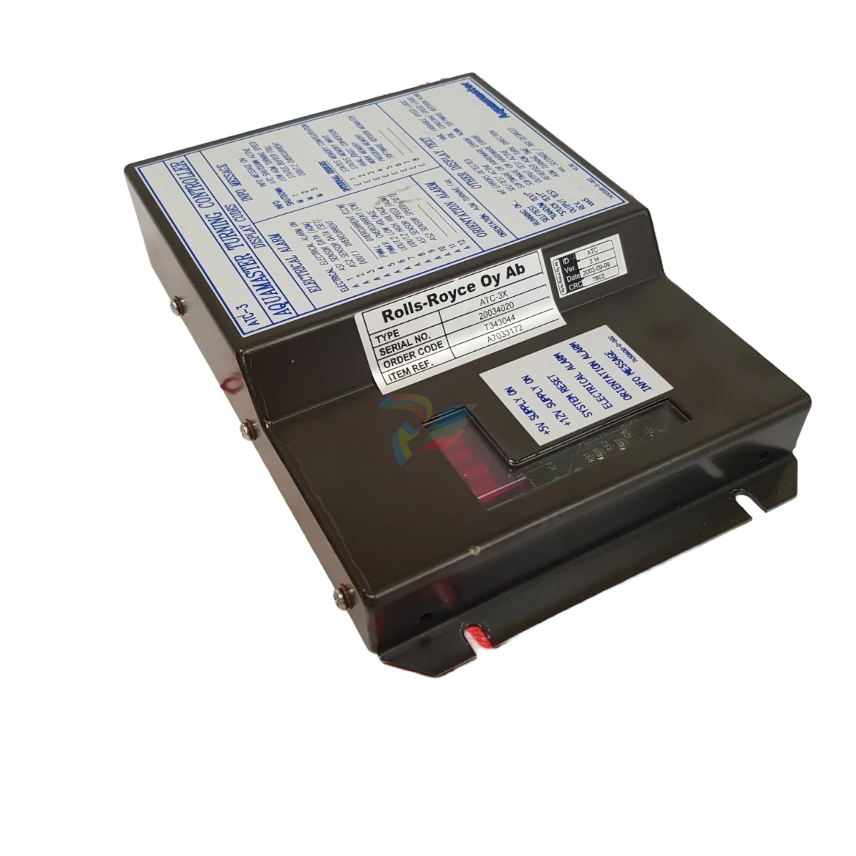
ROLLS-ROYCE ATC-3-A7033172 AQUAMASTER TURNING CONTROLLER
ROLLS-ROYCE ATC-3-A7033172 AQUAMASTER TURNING CONTROLLER
Pitch Indication
The Pitch Indication system is independent of the Normal Pitch Control system by
means of separate transmitters and electronic circuits. The pitch indicators are connected
in series and are driven from the Backup Control system.
Pitch Order Scaling
The system may need to reduce the pitch order for different reasons. The pitch reduction
can either be activated from a digital or anlogue input signal.
To reserve engine power to heavy consumers as alternators, fire pumps, etc., it may be
necessary to reduce the available propeller output power. This is normally done by
means of a fixed propeller pitch reduction.
If the drive motor is a diesel engine the system is prepared to handle a fuel limiter
contact, from the RPM governor (i.e. high scavange air pressure). If the contact is closed
the pitch order will stop increasing to a higher value, only decrease of pitch order against
zero is possible.
For azimuth thrusters, a pitch reduction will be activated if the azimuth order is changed
faster then the thruster azimuth servo can follow.
Thruster Azimuth Control
The azimuth control function is to obtain the correct thruster azimuth position in
accordance to the control lever order. Valve controlled hydraulic motors or frequency
controlled electro motors perform the positioning of the thruster azimuth.
Detailed information regarding the hydraulic system or motor data is available in the
Thruster Instruction manual
Normal Control
The azimuth controller computes the thruster position and order on the basis of signals
from the thruster feedback and control levers. A two-wiper linear potentiometer
provides two outputs with 90 degrees of phase shift named cosine and sine phase
respectively.
The lever order signals and feedback signals are monitored and verified against alarm
limits. If the signals exceed the limits this will release an alarm to the alarm plant with
a visual and audible system failure alarm on the manoeuvre stations.
Backup Control
The Backup Control system consists of closed loop control identical to the normal
control system. The Backup Control is a separate system, and is independent of the
Normal Control system. A system failure in the Normal Control system will
automatically switch to and engage the Backup Control.
Lever order signals and feedback are monitored and verified against adjustable alarm
limits. If the signals exceed the limits this will release an alarm to the alarm plant with
a visual and audible system failure alarm on the manoeuvre stations
Backup Control Operation
If a failure occurs on important parts of the Normal control for the Pitch/Azimuth/RPM
control function, the control will automatically be switched over to the backup control
system. A system failure audible and visible alarm will be activated on each of the
control panels.
The thruster control will continue to follow the lever in command, and command
transfer is done by using the common in command buttons. The command can be
transferred between all bridge position and the bridge control levers will continue to
work as in Normal Control.
A failure that occurs on important parts of the Backup control for the Pitch/Azimuth/
RPM control function, will not affect the Normal control system. If a system failure
occurs on the Backup Control an audible and visible alarm will be activated on each of
the control panels.
| User name | Member Level | Quantity | Specification | Purchase Date |
|---|


-
Hirschmann Industrial Ethernet Rail Switch RS20 Basic Family
-
GE Grid Solutions P40U Px40 USB Adaptor
-
ABB ontinuous Gas Analyzers AO2000 Series AO2040CU Ex Central Unit in Category 2G
-
ABB Advance Optima AO2000 Series Continuous gas analyzers Models AO2020. AO2040
-
ABB Advance Optima Module Uras 14
-
SAACKE control optimization
-
SAACKE se@vis efficiency monitor
-
SAACKE se@vis pro
-
SAACKE se@vis eco
-
SAACKE se@vis compact
-
HIRSCHMANN Industrial ETHERNET Switch MICE MS20/MS30
-
HIRSCHMANN MICE Media modules
-
Kongsberg GL-10 Level Switch
-
B&R ACOPOSinverter P74 frequency converter
-
Beckhoff CX2020 | Basic CPU module (service phase)
-
Beckhoff CX1010 | Basic CPU module (service phase)
-
Beckhoff CX5120 | Embedded PC with Intel Atom® E3815
-
Beckhoff CP69xx-xxxx-0010 | Economy built-in Control Panel with DVI/USB Extended interface
-
Beckhoff CP29xx-0000 | Multi-touch built-in Control Panel with DVI/USB Extended interface
-
SAACKE Monoblock Rotary Cup Burner SKVJ-M
-
ABB Plantguard Fault Tolerant Technology Architecture and Software
-
OMRON H8PR-8/H8PR-8P H8PR-16/H8PR-16P H8PR-24/H8PR-24P Rotary Positioner
-
ABB PFSA107-Z42 DTU Stressometer Digital Transmission Unit
-
Nidec Mentor MP
-
IBA PC connection for high-precision data acquisition with ibaNet-E
-
IBA FO Connection to Reflective Memory
-
IBA FO Connection to Siemens Systems
-
IBA Interface Cards For Fiber Optic Connections
-
IBA Field and Drive Buses
-
IBA ibaPADU-S Modular System
-
IBA ibaMAQS
-
STUCKE SYMAP®ARC
-
STUCKE SYMAP®R
-
STUCKE SYMAP®Compact
-
MOOG G123-825-001 BUFFER AMPLIFIER
-
Motorola MVME5100 Series VME Processor Modules
-
ABB MEASUREMENT & ANALYTICS NGC8209 Natural gas chromatograph
-
Motorola MVME162 Embedded Controller
-
HIMatrix Safety-Related Controller System Manual for the Modular Systems
-
MOTOROLA MVME2400 Series VME Processor Module
-
Sieger System 57
-
KONGSBERG MRU product line continuation
-
Woodward easYgen-3100/3200 Genset Control for Multiple Unit Operation
-
Woodward MFR 300 Multifunction Relay / Measuring
-
ABB AX410, AX411, AX416, AX450 and AX455 Single and dual input analyzers
-
Woodward easYgen-1400 Technical Manual Genset Control
-
Woodward easYgen-400 Operation Manual Genset Control
-
Woodward High Output Digital Valve Positioner (DVP) DVP5000/DVP10000/DVP12000
-
Woodward High Output Digital Valve Positioner DVP5000 and DVP10000
-
Woodward TG611-13/-17 Overspeed Test Device Conversion Kit
-
Woodward MicroNet Safety Module (MSM)
-
Woodward 2301A Electronic Load Sharing and Speed Control 9905/9907 Series
-
Woodward-Service Bulletin 01671
-
UniOP eTOP40B 12.1” TFT color display
-
UniOP eTOP40 TFT Color display
-
UniOP eTOP33B 10.4” TFT color display
-
UniOP eTOP33C eTOP33-0050 Resistive touchscreen
-
UniOP eTOP30. eTOP32 eTOP32-0050 Human-machine interface equipment
-
UniOP eTOP20B and eTOP21B eTOP20B-0050
-
UniOP eTOP12 eTOP12-0050 Advanced human-machine interface equipment
-
UniOP eTOP11 eTOP11-0050 HMI
-
UniOP eTOP06 HMI
-
UniOP eTOP05EB eTOP05EB-DF45 HMI
-
UniOP eTOP05. eTOP05P Human-machine interface equipment
-
UniOP eTOP03 eTOP03-0046
-
UniOP eTOP507 507U2P1 eTOP Series 500 Human-Machine Interface
-
UniOP eTOP307
-
UniOP ePAD32B, ePAD33B and ePAD33BT ePAD33B-0350
-
UniOP ePAD05 and ePAD06
-
UniOP ePAD04 ePAD04-D046 Universal Operator Panel
-
UniOP ePAD03 and ePAD04
-
UniOP CP02F-02, CP02R-04
-
UniOP CP01R-04 Compact Human-Interface Device
-
UniOP ERT-16 - Industrial PLC Workstation
-
UniOP ePAD03 and ePAD04
-
UNIOP EPALM10-DA71 state-of-the-art handheld HMI
-
Watlow SERIES CLS200 SPECIFICATION SHEET
-
Detailed Explanation of B&R Power Panel 300/400: The Core of Industrial Automation Control
-
YOKOGAWA Models ANB10S, ANB10D, ANR10S, ANR10D Node Units (for FIO)
-
Woodward ESDR 4 Current Differential Protection Relay
-
Woodward easYgen-3000 Genset Control for
-
Woodward CPC-II Current-to-Pressure Converter
-
Woodward 8290-189-EPG-installation-manual 8290-044
-
Woodward Product Change Notification 06946A
-
Woodward Product Change Notification 06912
-
Fisher™ 4660 High-Low Pressure Pilot
-
Flexible digital protection and control equipment SYMAP®
-
Woodward 723PLUS Digital Control
-
Woodward 505 Digital Controller For steam turbineses
-
Woodward 85018V2 505E Digital Governor for Extraction Steam Turbines
-
Woodward 85018V1 Turbine Control Parameters
-
Woodward 26871 505 Enhanced Digital Control for Steam Turbines
-
Woodward 03365 505E (Extraction / Admission)
-
KONGSBERG RMP420-Remote Multipurpose Input/Output
-
KONGSBERG RCU501 Remote Controller Unit
-
KONGSBERG RCU500 Remote Controller Unit
-
K-Gauge TOP KONGSBERG Tank Overfill Protection SystemFeatures
-
Kongsberg DPS112 DGNSS (DGPS/DGLONASS) sensor
-
Kongsberg d0000930 presafe-atex-report signed
-
HIMax TECHNICAL FACTS X Series
-
GE Multilin F650
-
GE MIF II - Legacy
-
GE PQM II Power QualIty Meter
-
Hydran 201Ti Mark IV Essential DGA monitoring for transformers
-
alstom AMS42/84 5B Amplifier SystemAmplifier Technology at its Best.
-
GE VMIVME-5576 Fiber-Optic Reflective Memory with Interrupts
-
GE Multilin 750/760 - Legacy Feeder Protection System
-
GE Fanuc Automation VMICPCI-7806 Specifications
-
GE VMIVME-7807 VME-7807RC* Intel® Pentium® M-Based VME SBC
-
GE Fanuc Automation VMIVME-7750 Specifications
-
FOXBORO Compact FBM240. Redundant with Readback, Discrete
-
FOXBORO FBM208/b, Redundant with Readback, 0 to 20 mA I/O Module
-
FOXBORO FBM201e Analog Input (0 to 20 mA) Interface Modules
-
Foxboro DCS FBM206 Pulse Input Module
-
FOXBORO FBM216 HART® Communication Redundant Input Interface Module
-
FOXBORO Z-Module Control Processor 270 (ZCP270)
-
Foxboro DCS Compact FBM241/c/d, Redundant, Discrete I/O Modules
-
Foxboro FBM223 PROFIBUS-DP™ Communication Interface Module
-
Foxboro DCS FBM204. 0 to 20 mAI/OModule
-
Foxboro FBM239, Discrete 16DI/16DO Module
-
Foxboro FBM202 Thermocouple/mV Input Module
-
Foxboro E69F Current-to-Pneumatic Signal Converter
-
EMERSON M-series Intrinsically Safe I/O
-
Configuration for AMS 6500 Protection Monitors
-
EMERSON DeltaV™ M-series Traditional I/O
-
EMERSON DeltaV™ SQ Controller
-
AEROTECH Ndrive MP Hardware Manual
-
AEROTECH Ndrive HPe 10/20/30
Add: High-tech Software Park, Xiamen City, Fujian Province
Mobile: +86-17750019513(WhatsApp)
Email: yy4291644@gmail.com
Website: https://www.abb-sis.com
.jpg)
.jpg)
.jpg)
.jpg)
.jpg)
.jpg)

-
ROLLS-ROYCE CCN 01 & ROLLS-ROYCE SLIO 02 CANMAN CONTROLLER NETWORK
-
ROLLS-ROYCE ATC-3-A7033172 AQUAMASTER TURNING CONTROLLER
-
ROLLS-ROYCE POSCON V.3 JOYSTICK MODULE 6459
-
Rolls-Royce Marine 389-496-00 Joystick Remote Control Panel 6799-W, 389-996-00
-
Rolls-Royce data respons 10.4'' Panel Computer 98H010A0000I/R10I53S
