


- SHINKAWA
- Beckhoff
- CTI
- Basler Electric
- ETEL
- Jaquet
- ADLINK
- SEL
- UNIOP
- Sieger
- Autronica
- SAMSUNG
- Stucke Elektronik
- Moore
- NI
- EMERSON
- IBA
- SST
- LEYBELOD
- SAMSUNG
- METSO
- AMAT
- Phoenix
- LAND
- LAMBDA
- Abaco
- Kongsberg
- ALFA LAVAL
- Pacific Scientific
- Others
- OMRON
- AMAT
- ICS Triplex
- Lam Research
- KUKA
- Hirschmann
- ELAU
- EATON
- Applicom
- Watlow Anafaze
- Meggitt Vibro-meter
- Carrier
- Other
- ROCKWELL
- Rolls-Royce
- SAACKE
- Yokogawa
- B&R
- Reliance Electric
- Seifert
- A-B
- Weimeide Metso
- KEBA
- HIMatrix
- Valmet
- Schneider
- Prosoft
- PEPPERL+FUCHS
- Honeywell
- Woodward
- GE
- GEA Westfalia Separator
- Bently Nevada
- ALSTOM
- Foxboro
- MOTOROLA
- Fanuc
- VMIC
- KOLLMORGEN
- SEW
- Rexroth
- AEROTECH
- TOSHIBA
- TmeIC
- Sumitomo
- SOCAPEL SOCASIN
- SMC
- Stromag
- SIEMENS
- SCHUMACHER
- ABB
- MOOG
- EPRO
- EMERSON
- Triconex
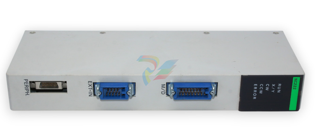
OMRON C500-NC222-E PLC
OMRON C500-NC222-E PLC
Memory Packs
The Memory Pack fits into the slot located on the left side of the CPU. Be
cause the Memory Pack is not provided with the PC upon delivery, a Memory
Pack must be selected and installed in the CPU. There are two Memory
Packs available, either RAM or ROM, that can be used in the C500H PC.
RAM Pack
Data can be randomly written to and read from the RAM Pack, making it pos
sible to enter your own program into the CPU. However, because this is not a
fixed program, the memory of the RAM Pack is erased when power is not
supplied to the CPU or when the RAM Pack is removed from the CPU.
Two models of RAM Packs are available, which vary in memory capacity:
16K, and 24K words. Refer to Appendix C Standard Models for model num
bers.
Using a Programming Console, execute FUN (01) and a search operation to
check the amount of memory available
Data contained in the ROM Pack is stored on EPROM chips and cannot be
altered or erased during the CPU's operation. Write the user's program to the
EPROM chips and mount the chips (3 max.) on the ROM chip. The entire
pack is installed in the CPU. Once the data is written to the chip the data will
not be lost when the power to the PC is OFF
When we speak of a PC, we usually think of it as a single object. But actually
even the simplest PCs are usually composed of several different devices. In
fact a single PC can be physically spread throughout a building, but we still
call it one PC.
In this section, we will start with a Backplane and use all the Units discussed
in Section 2 Description of All Components to build a PC.
There is no single Unit that can be said to constitute a Rack PC. To build a
Rack PC, we start with a Backplane. The Backplane for the C500 is shown
below.
The Backplane is a simple device having two functions. The first is to provide
physical support for the Units to be mounted to it. The second is to provide
the connectors and electrical pathways necessary for connecting the Units
mounted to it.
The first device we will add to the Backplane is a Power Supply. The Power
Supply fits into the rightmost position on the Backplane and provides electric
ity at the voltages required by the other Units of the PC. It can also be used
to power devices other than the PC if necessary.
Power Supply
The core of the PC is the CPU. The CPU contains the program consisting of
the series of steps necessary for the control task. The CPU fits into the posi
tion directly to the left of the Power Supply
Unlike the CPU of the Package-type PC, the CPU of the Rack PC has no I/O
points built in. So, in order to complete this kind of PC we need to mount one
or more I/O Units to the Backplane. Mount the I/O Units to the Backplane by
pressing the I/O Unit firmly into position, making sure the connectors are
properly mated. Secure the Unit by tightening the mounting screws located
on the top and bottom of the Unit
I/O Units are where the control connections are made from the PC to all the
various input devices and output devices. As you can see from the figure,
there is still some space available on the right side of the Backplane. This
space is for any additional I/O Units that may be required
The figure above shows a total of eight I/O Units mounted to the Backplane.
Backplanes are available in different lengths, and can hold a different number
of I/O Units accordingly. Of course, not all I/O Units look exactly alike, but the
ones in the figure show their typical appearance. This configuration of Back
plane, Power Supply, CPU, and I/O Units is called a CPU Rack. This term
refers to the Backplane and all the Units mounted to it. However, if we want
to include more than eight I/O Units in our configuration we can add an addi
| User name | Member Level | Quantity | Specification | Purchase Date |
|---|


-
CTI 2500 Series® Slice Ethernet Remote I/O System
-
CTI 500 Series® Compact Programmable Automation Control System
-
CTI 2500 Series® Classic Programmable Automation Control System
-
CTI 2500 Series® Bases
-
SHINKAWA VM-25 Condition Monitoring System UPDATED
-
SHINKAWA VM-5 SERIES OPTIONS
-
ABB SACO 64D4 Annunciator unit
-
ABB SPAU 140 C Synchro-check relay
-
HONEYWELL TDC 3000X Advanced Process Manager
-
HONEYWELL ENHANCED MICRO TDC 3000
-
VIBRO-METER VM600Mk2/ VM600 XMx16 + XIO16T extended condition monitoring modules
-
VIBRO-METER VM600Mk2/ VM600 RPS6U rack power supplies
-
VIBRO-METER VM600Mk2/ VM600 ABE056 slimline rack
-
VIBRO-METER VM600Mk2 RLC16Mk2 relay modules
-
VIBRO-METER VM600Mk2 MPC4Mk2 + IOC4Mk2 machinery protection and condition monitoring modules
-
VIBRO-METER VM600Mk2 CPUMMk2 + IOCNMk2 rack controller and communications interface module
-
VIBRO-METER VM600Mk2 CPUMMk2 + IOCNMk2 rack controller and communications interface module
-
ADLINK cPCI-8168 Advanced 6U CompactPCI 8-axis Motion Controller with One HSL Network
-
ADLINK PCI/PCIe-7300A, cPCI-7300 32-CH 80 MB/s High-Speed Digital I/O Cards
-
ADLINK cPCI-7248/7249R 48-CH DIO & Timer/Counter Cards
-
ADLINK PCI-7230/7233/7234. LPCI/LPCIe/cPCI-7230 32-CH Isolated DIO Cards
-
ADLINK cPCI-6965 Series Value 6U CompactPCI® Intel® Core™2 Duo
-
ADLINK cPCI-6910 Series 6U CompactPCI® Dual-Core Intel® Xeon® Processor LV / ULV Universal Blade
-
ADLINK CPCI-6670 6U CompactPCI Low Power Pentium® III SBC
-
ADLINK cPCI-6625/6 Series6U CompactPCI® PlusIO blade with Intel® Core™ i7/i3 Processor
-
ADLINK 3U CompactPCI CPU Modules
-
ADLINK CM-435 Extreme Rugged™ PC/104 Single Board Computer
-
ADLINK Centralized Motion Controllers PCI-8254/8258
-
ADLINK NuPRO-E43 PICMG® 1.3 Full-Size LGA1151 with 6th/7th Generation Intel® Core™ i7/i5/i3o
-
ADLINK DLAP-211-JNX/DLAP-211-JT2/ DLAP-211-Nano
-
نظام التحكم الرقمي في التحفيز الكهربائي BASLER DECS-200
-
Hirschmann RS30-1602O6O6SDAE compact OpenRail managed Ethernet switches
-
Hirschmann RS30-0802O6O6SDAE Ethernet switch
-
Hirschmann RS20-1600T1T1SDAE Management-type Ethernet switch
-
Hirschmann OCTOPUS 24M Limited Availability/Passive
-
Hirschmann MSP30-24040SCZ9MRHHE3A
-
Hirschmann MAR1040-4C4C4C4C9999SMMHRHHXX.X. Gigabit Ethernet Switch configurator
-
Hirschmann Industrial Ethernet Rail Switch SPIDER II, SPIDER II Giga, SPIDER II PoE
-
Hirschmann Industrial Ethernet Firewall EAGLE One
-
Hirschmann Industrial Security Router EAGLE20/30
-
Hirschmann Description and operating instructions RS2-xTX/xFX EEC
-
Basler Electric DIGITAL EXCITATION CONTROL SYSTEM DECS-300
-
Basler Electric DECS-200 Digital Excitation Control System
-
Basler Electric GENERATOR PROTECTION SYSTEM BE1-GPS100
-
Jaquet FT3000 Speed measurement system
-
Hirschmann Industrial Ethernet Ruggedized Switch MACH1000 Family
-
Basler Electric BESTCOMSPlus®
-
ETEL AccurET MODULAR 300 EA-P2M-300-xxxxxA controller
-
Basler Electric ES Series Protection Relays
-
ABB Multifunction Protection and Switchbay Control Unit REF542plus
-
EMERSON AMS 2140 Machinery Health Analyzer
-
Hirschmann Industrial Ethernet Rail Switch RS20 Basic Family
-
GE Grid Solutions P40U Px40 USB Adaptor
-
ABB ontinuous Gas Analyzers AO2000 Series AO2040CU Ex Central Unit in Category 2G
-
ABB Advance Optima AO2000 Series Continuous gas analyzers Models AO2020. AO2040
-
ABB Advance Optima Module Uras 14
-
SAACKE control optimization
-
SAACKE se@vis efficiency monitor
-
SAACKE se@vis pro
-
SAACKE se@vis eco
-
SAACKE se@vis compact
-
HIRSCHMANN Industrial ETHERNET Switch MICE MS20/MS30
-
HIRSCHMANN MICE Media modules
-
Kongsberg GL-10 Level Switch
-
B&R ACOPOSinverter P74 frequency converter
-
Beckhoff CX2020 | Basic CPU module (service phase)
-
Beckhoff CX1010 | Basic CPU module (service phase)
-
Beckhoff CX5120 | Embedded PC with Intel Atom® E3815
-
Beckhoff CP69xx-xxxx-0010 | Economy built-in Control Panel with DVI/USB Extended interface
-
Beckhoff CP29xx-0000 | Multi-touch built-in Control Panel with DVI/USB Extended interface
-
SAACKE Monoblock Rotary Cup Burner SKVJ-M
-
ABB Plantguard Fault Tolerant Technology Architecture and Software
-
OMRON H8PR-8/H8PR-8P H8PR-16/H8PR-16P H8PR-24/H8PR-24P Rotary Positioner
-
ABB PFSA107-Z42 DTU Stressometer Digital Transmission Unit
-
Nidec Mentor MP
-
IBA PC connection for high-precision data acquisition with ibaNet-E
-
IBA FO Connection to Reflective Memory
-
IBA FO Connection to Siemens Systems
-
IBA Interface Cards For Fiber Optic Connections
-
IBA Field and Drive Buses
-
IBA ibaPADU-S Modular System
-
IBA ibaMAQS
-
STUCKE SYMAP®ARC
-
STUCKE SYMAP®R
-
STUCKE SYMAP®Compact
-
MOOG G123-825-001 BUFFER AMPLIFIER
-
Motorola MVME5100 Series VME Processor Modules
-
ABB MEASUREMENT & ANALYTICS NGC8209 Natural gas chromatograph
-
Motorola MVME162 Embedded Controller
-
HIMatrix Safety-Related Controller System Manual for the Modular Systems
-
MOTOROLA MVME2400 Series VME Processor Module
-
Sieger System 57
-
KONGSBERG MRU product line continuation
-
Woodward easYgen-3100/3200 Genset Control for Multiple Unit Operation
-
Woodward MFR 300 Multifunction Relay / Measuring
-
ABB AX410, AX411, AX416, AX450 and AX455 Single and dual input analyzers
-
Woodward easYgen-1400 Technical Manual Genset Control
-
Woodward easYgen-400 Operation Manual Genset Control
-
Woodward High Output Digital Valve Positioner (DVP) DVP5000/DVP10000/DVP12000
-
Woodward High Output Digital Valve Positioner DVP5000 and DVP10000
-
Woodward TG611-13/-17 Overspeed Test Device Conversion Kit
-
Woodward MicroNet Safety Module (MSM)
-
Woodward 2301A Electronic Load Sharing and Speed Control 9905/9907 Series
-
Woodward-Service Bulletin 01671
-
UniOP eTOP40B 12.1” TFT color display
-
UniOP eTOP40 TFT Color display
-
UniOP eTOP33B 10.4” TFT color display
-
UniOP eTOP33C eTOP33-0050 Resistive touchscreen
-
UniOP eTOP30. eTOP32 eTOP32-0050 Human-machine interface equipment
-
UniOP eTOP20B and eTOP21B eTOP20B-0050
-
UniOP eTOP12 eTOP12-0050 Advanced human-machine interface equipment
-
UniOP eTOP11 eTOP11-0050 HMI
-
UniOP eTOP06 HMI
-
UniOP eTOP05EB eTOP05EB-DF45 HMI
-
UniOP eTOP05. eTOP05P Human-machine interface equipment
-
UniOP eTOP03 eTOP03-0046
-
UniOP eTOP507 507U2P1 eTOP Series 500 Human-Machine Interface
-
UniOP eTOP307
-
UniOP ePAD32B, ePAD33B and ePAD33BT ePAD33B-0350
-
UniOP ePAD05 and ePAD06
-
UniOP ePAD04 ePAD04-D046 Universal Operator Panel
-
UniOP ePAD03 and ePAD04
-
UniOP CP02F-02, CP02R-04
-
UniOP CP01R-04 Compact Human-Interface Device
-
UniOP ERT-16 - Industrial PLC Workstation
-
UniOP ePAD03 and ePAD04
-
UNIOP EPALM10-DA71 state-of-the-art handheld HMI
-
Watlow SERIES CLS200 SPECIFICATION SHEET

Add: High-tech Software Park, Xiamen City, Fujian Province
Mobile: +86-17750019513(WhatsApp)
Email: yy4291644@gmail.com
Website: https://www.abb-sis.com
.jpg)
.jpg)
.jpg)
.jpg)
.jpg)
.jpg)

-
AEROTECH SM Series High-Performance Stepper Motors
-
AEROTECH BLMSC Series Linear Motors
-
AEROTECH Custom Linear Motors
-
AEROTECH BMS Series Brushless, Slotless Rotary Motors
-
AEROTECH BM Series Brushless Rotary Motors
