


- Basler Electric
- Jaquet
- Beckhoff
- ETEL
- UNIOP
- Sieger
- Autronica
- SAMSUNG
- Stucke Elektronik
- Moore
- NI
- EMERSON
- IBA
- SST
- LEYBELOD
- SAMSUNG
- METSO
- AMAT
- Phoenix
- LAND
- LAMBDA
- Abaco
- Kongsberg
- ALFA LAVAL
- Pacific Scientific
- Others
- OMRON
- AMAT
- ICS Triplex
- Lam Research
- KUKA
- Hirschmann
- ELAU
- EATON
- Applicom
- Watlow Anafaze
- Meggitt Vibro-meter
- Carrier
- Other
- ROCKWELL
- Rolls-Royce
- SAACKE
- Yokogawa
- B&R
- Reliance Electric
- Seifert
- A-B
- Weimeide Metso
- KEBA
- HIMatrix
- Valmet
- Schneider
- Prosoft
- PEPPERL+FUCHS
- Honeywell
- Woodward
- GE
- GEA Westfalia Separator
- Bently Nevada
- ALSTOM
- Foxboro
- MOTOROLA
- Fanuc
- VMIC
- KOLLMORGEN
- SEW
- Rexroth
- AEROTECH
- TOSHIBA
- TmeIC
- Sumitomo
- SOCAPEL SOCASIN
- SMC
- Stromag
- SIEMENS
- SCHUMACHER
- ABB
- MOOG
- EPRO
- EMERSON
- Triconex
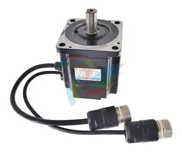
OMRON SGMPH-04AAA61D-OY Servo Motor
USB-Serial Conversion Cable
Applicable OS
Windows XP/Vista/7/8/10 *1
Applicable software CX-Thermo version 4.62 or higher
Applicable models
E5@C-T Series, E5@C Series, and E5CB Series
USB interface standard Conforms to USB Specification 2.0
DTE speed
Connector
specifications
Power supply
38.400 bps
Computer: USB (Type A plug)
Digital Temperature Controller: Special serial
connector
Bus power (Supplied from the USB host controller) *2
Power supply voltage 5 VDC
Current
consumption
Output voltage
Output current
Ambient operating
temperature
Ambient operating
humidity
450 mA max.
4.7±0.2 VDC (Supplied from USB-Serial Conversion
Cable to the Digital Temperature Controller.)
250 mA max. (Supplied from USB-Serial Conversion
Cable to the Digital Temperature Controller.)
0 to 55°C (with no condensation or icing)
10% to 80%
Storage temperature −20 to 60°C (with no condensation or icing)
Storage humidity
10% to 80%
Altitude
Weight
2.000 m max.
Approx. 120 g
Windows is a registered trademark of Microsoft Corporation in the
United States and or other countries.
*1.CX-Thermo version 4.65 or higher runs on Windows 10.
*2.Use a high-power port for the USB port.
Note: A driver must be installed on the computer. Refer to the Instruction
Manual included with the Cable for the installation procedure.
Communications Specifications
Transmission line
connection method
Communications
RS-485: Multidrop
RS-485 (two-wire, half duplex)
Synchronization method Start-stop synchronization
Protocol
Component
Communi
cations
Copying *
When Digital Temperature Controllers are connected,
set points and RUN/STOP commands can be sent
from the Digital Temperature Controller that is set as
the master to the Digital Temperature Controllers that
are set as slaves.
Slope and offsets can be set for the set point.
Number of connected Digital Temperature
Controllers: 32 max. (including master)
When Digital Temperature Controllers are connected,
the parameters can be copied from the Digital
Temperature Controller that is set as the master to the
Digital Temperature Controllers that are set as slaves.
MELSEC is a registered trademark of Mitsubishi Electric Corporation.
KEYENCE is a registered trademark of Keyence Corporation.
*Both the programless communications and the component
communications support the copying.
Current Transformer (Order Separately)
Ratings
E54-CT1
E54-CT3
E54-CT1L
E54-CT3L
| IS215VAMBH1A GE Acoustic Monitoring board |
| IS215UCVGM09B GE single slot controller/processor |
| IS215UCVGM09A GE Drive Local Area Network Plus (DLAN+) Card |
| IS215UCVGM09 GE Drive Local Area Network Plus (DLAN+) Card |
| IS215UCVGM01A GE UCV controller board |
| IS215UCVFH2A GE UCV Controller |
| IS215UCVEM08 PROCESSOR BOARD TYPE US2000 GE |
| IS230TRLSH1B GE Mark VI Input-Output Board |
| IS230TPROH2C GE mergency Protection Terminal board |
| IS230TNAIH4C GE Analog I/O card that allows DIN-rail mounting |
| IS230TCISH9C GE I/O terminal board module with DIN-rail mounting |
| IS230TCISH7C GE functions as an I/O terminal board |
| IS230TBTCH1B GE small board component |
| IS220PSFDH1A GE housed within a rectangular enclosure |
| IS220PPRFH1A GE labeled a Profibus Master Gateway Analog I/O Pack |
| IS220PIOAH1A GE PIOA ARCNET Interface Module |
| IS230TRTDH1D GE RTD Input terminal board |
| IS220PDIOH1B GE Discrete Input/Output (I/O) Modules/Packs |
| IS200AEBMG1AFB GE Control Card w/CIMPLICITY |
Dielectric strength 1.000 VAC for 1 min
Vibration resistance
1.500 VAC for 1 min
50 Hz, 98 m/s2
Weight
Accessories
E54-CT1: Approx. 11.5 g
E54-CT3: Approx. 50 g
E54-CT3 Only
Armatures (2)
Plugs (2)
E54-CT1L: Approx. 14 g
E54-CT3L: Approx. 57 g
None
Heater Burnout Alarms and SSR Failure
Alarms
CT input (for heater
current detection)
Models with detection for single-phase
heaters: One input
Maximum heater current 50 A AC
Input current
indication accuracy
±5% FS ±1 digit max.
Heater burnout alarm
setting range *1
CompoWay/F, or Modbus
Baud rate *
Transmission code
9.600. 19.200. 38.400. or 57.600 bps
ASCII
SSR failure alarm setting
range *2
0.1 to 49.9 A (in units of 0.1 A)
Minimum detection ON time: 100 ms *3
Data bit length *
Stop bit length *
Error detection
Flow control
Interface
Retry function
7 or 8 bits
1 or 2 bits
Vertical parity (none, even, odd)
Block check character (BCC)
with CompoWay/F or
CRC-16 with Modbus
None
RS-485
None
0.1 to 49.9 A (in units of 0.1 A)
Minimum detection OFF time: 100 ms
*4
*1.For heater burnout alarms, the heater current will be measured
when the control output is ON, and the output will turn ON if the
heater current is lower than the set value (i.e., heater burnout
detection current value).
*2.For SSR failure alarms, the heater current will be measured when
the control output is OFF, and the output will turn ON if the heater
current is higher than the set value (i.e., SSR failure detection
current value).
*3.The value is 30 ms for a control period of 0.1 s or 0.2 s.
*4.The value is 35 ms for a control period of 0.1 s or 0.2 s.
Communications buffer
Communications
response wait time
217 bytes
0 to 99 ms
Default: 20 ms
*The baud rate, data bit length, stop bit length, and vertical parity can
be individually set using the Communications Setting Level.
Communications Functions
Programless
communica
tions
10
You can use the memory in the PLC to read and write
E5@C parameters, start and stop operation, etc.
The E5@C automatically performs communications with
PLCs. No communications programming is required.
Number of connected Digital Temperature
Controllers: 32 max. (Up to 16 for the FX Series)
Applicable PLCs
OMRON PLCs
CS Series, CJ Series, CP
Series, NJ Series, or NX1P
Mitsubishi Electric PLCs MELSEC Q Series, L Series,
FX3 Series, or iQ-R Series
KEYENCE PLCs
KEYENCE KV Series
| User name | Member Level | Quantity | Specification | Purchase Date |
|---|


-
نظام التحكم الرقمي في التحفيز الكهربائي BASLER DECS-200
-
Hirschmann RS30-1602O6O6SDAE compact OpenRail managed Ethernet switches
-
Hirschmann RS30-0802O6O6SDAE Ethernet switch
-
Hirschmann RS20-1600T1T1SDAE Management-type Ethernet switch
-
Hirschmann OCTOPUS 24M Limited Availability/Passive
-
Hirschmann MSP30-24040SCZ9MRHHE3A
-
Hirschmann MAR1040-4C4C4C4C9999SMMHRHHXX.X. Gigabit Ethernet Switch configurator
-
Hirschmann Industrial Ethernet Rail Switch SPIDER II, SPIDER II Giga, SPIDER II PoE
-
Hirschmann Industrial Ethernet Firewall EAGLE One
-
Hirschmann Industrial Security Router EAGLE20/30
-
Hirschmann Description and operating instructions RS2-xTX/xFX EEC
-
Basler Electric DIGITAL EXCITATION CONTROL SYSTEM DECS-300
-
Basler Electric DECS-200 Digital Excitation Control System
-
Basler Electric GENERATOR PROTECTION SYSTEM BE1-GPS100
-
Jaquet FT3000 Speed measurement system
-
Hirschmann Industrial Ethernet Ruggedized Switch MACH1000 Family
-
Basler Electric BESTCOMSPlus®
-
ETEL AccurET MODULAR 300 EA-P2M-300-xxxxxA controller
-
Basler Electric ES Series Protection Relays
-
ABB Multifunction Protection and Switchbay Control Unit REF542plus
-
EMERSON AMS 2140 Machinery Health Analyzer
-
Hirschmann Industrial Ethernet Rail Switch RS20 Basic Family
-
GE Grid Solutions P40U Px40 USB Adaptor
-
ABB ontinuous Gas Analyzers AO2000 Series AO2040CU Ex Central Unit in Category 2G
-
ABB Advance Optima AO2000 Series Continuous gas analyzers Models AO2020. AO2040
-
ABB Advance Optima Module Uras 14
-
SAACKE control optimization
-
SAACKE se@vis efficiency monitor
-
SAACKE se@vis pro
-
SAACKE se@vis eco
-
SAACKE se@vis compact
-
HIRSCHMANN Industrial ETHERNET Switch MICE MS20/MS30
-
HIRSCHMANN MICE Media modules
-
Kongsberg GL-10 Level Switch
-
B&R ACOPOSinverter P74 frequency converter
-
Beckhoff CX2020 | Basic CPU module (service phase)
-
Beckhoff CX1010 | Basic CPU module (service phase)
-
Beckhoff CX5120 | Embedded PC with Intel Atom® E3815
-
Beckhoff CP69xx-xxxx-0010 | Economy built-in Control Panel with DVI/USB Extended interface
-
Beckhoff CP29xx-0000 | Multi-touch built-in Control Panel with DVI/USB Extended interface
-
SAACKE Monoblock Rotary Cup Burner SKVJ-M
-
ABB Plantguard Fault Tolerant Technology Architecture and Software
-
OMRON H8PR-8/H8PR-8P H8PR-16/H8PR-16P H8PR-24/H8PR-24P Rotary Positioner
-
ABB PFSA107-Z42 DTU Stressometer Digital Transmission Unit
-
Nidec Mentor MP
-
IBA PC connection for high-precision data acquisition with ibaNet-E
-
IBA FO Connection to Reflective Memory
-
IBA FO Connection to Siemens Systems
-
IBA Interface Cards For Fiber Optic Connections
-
IBA Field and Drive Buses
-
IBA ibaPADU-S Modular System
-
IBA ibaMAQS
-
STUCKE SYMAP®ARC
-
STUCKE SYMAP®R
-
STUCKE SYMAP®Compact
-
MOOG G123-825-001 BUFFER AMPLIFIER
-
Motorola MVME5100 Series VME Processor Modules
-
ABB MEASUREMENT & ANALYTICS NGC8209 Natural gas chromatograph
-
Motorola MVME162 Embedded Controller
-
HIMatrix Safety-Related Controller System Manual for the Modular Systems
-
MOTOROLA MVME2400 Series VME Processor Module
-
Sieger System 57
-
KONGSBERG MRU product line continuation
-
Woodward easYgen-3100/3200 Genset Control for Multiple Unit Operation
-
Woodward MFR 300 Multifunction Relay / Measuring
-
ABB AX410, AX411, AX416, AX450 and AX455 Single and dual input analyzers
-
Woodward easYgen-1400 Technical Manual Genset Control
-
Woodward easYgen-400 Operation Manual Genset Control
-
Woodward High Output Digital Valve Positioner (DVP) DVP5000/DVP10000/DVP12000
-
Woodward High Output Digital Valve Positioner DVP5000 and DVP10000
-
Woodward TG611-13/-17 Overspeed Test Device Conversion Kit
-
Woodward MicroNet Safety Module (MSM)
-
Woodward 2301A Electronic Load Sharing and Speed Control 9905/9907 Series
-
Woodward-Service Bulletin 01671
-
UniOP eTOP40B 12.1” TFT color display
-
UniOP eTOP40 TFT Color display
-
UniOP eTOP33B 10.4” TFT color display
-
UniOP eTOP33C eTOP33-0050 Resistive touchscreen
-
UniOP eTOP30. eTOP32 eTOP32-0050 Human-machine interface equipment
-
UniOP eTOP20B and eTOP21B eTOP20B-0050
-
UniOP eTOP12 eTOP12-0050 Advanced human-machine interface equipment
-
UniOP eTOP11 eTOP11-0050 HMI
-
UniOP eTOP06 HMI
-
UniOP eTOP05EB eTOP05EB-DF45 HMI
-
UniOP eTOP05. eTOP05P Human-machine interface equipment
-
UniOP eTOP03 eTOP03-0046
-
UniOP eTOP507 507U2P1 eTOP Series 500 Human-Machine Interface
-
UniOP eTOP307
-
UniOP ePAD32B, ePAD33B and ePAD33BT ePAD33B-0350
-
UniOP ePAD05 and ePAD06
-
UniOP ePAD04 ePAD04-D046 Universal Operator Panel
-
UniOP ePAD03 and ePAD04
-
UniOP CP02F-02, CP02R-04
-
UniOP CP01R-04 Compact Human-Interface Device
-
UniOP ERT-16 - Industrial PLC Workstation
-
UniOP ePAD03 and ePAD04
-
UNIOP EPALM10-DA71 state-of-the-art handheld HMI
-
Watlow SERIES CLS200 SPECIFICATION SHEET
-
Detailed Explanation of B&R Power Panel 300/400: The Core of Industrial Automation Control
-
YOKOGAWA Models ANB10S, ANB10D, ANR10S, ANR10D Node Units (for FIO)
-
Woodward ESDR 4 Current Differential Protection Relay
-
Woodward easYgen-3000 Genset Control for
-
Woodward CPC-II Current-to-Pressure Converter
-
Woodward 8290-189-EPG-installation-manual 8290-044
-
Woodward Product Change Notification 06946A
-
Woodward Product Change Notification 06912
-
Fisher™ 4660 High-Low Pressure Pilot
-
Flexible digital protection and control equipment SYMAP®
-
Woodward 723PLUS Digital Control
-
Woodward 505 Digital Controller For steam turbineses
-
Woodward 85018V2 505E Digital Governor for Extraction Steam Turbines
-
Woodward 85018V1 Turbine Control Parameters
-
Woodward 26871 505 Enhanced Digital Control for Steam Turbines
-
Woodward 03365 505E (Extraction / Admission)
-
KONGSBERG RMP420-Remote Multipurpose Input/Output
-
KONGSBERG RCU501 Remote Controller Unit
-
KONGSBERG RCU500 Remote Controller Unit
-
K-Gauge TOP KONGSBERG Tank Overfill Protection SystemFeatures
-
Kongsberg DPS112 DGNSS (DGPS/DGLONASS) sensor
-
Kongsberg d0000930 presafe-atex-report signed
-
HIMax TECHNICAL FACTS X Series
-
GE Multilin F650
-
GE MIF II - Legacy
-
GE PQM II Power QualIty Meter
-
Hydran 201Ti Mark IV Essential DGA monitoring for transformers
-
alstom AMS42/84 5B Amplifier SystemAmplifier Technology at its Best.
-
GE VMIVME-5576 Fiber-Optic Reflective Memory with Interrupts
-
GE Multilin 750/760 - Legacy Feeder Protection System
Add: High-tech Software Park, Xiamen City, Fujian Province
Mobile: +86-17750019513(WhatsApp)
Email: yy4291644@gmail.com
Website: https://www.abb-sis.com
.jpg)
.jpg)
.jpg)
.jpg)
.jpg)
.jpg)

-
HIRSCHMANN RS20-1600S2S2SDAEHH09.0.14 Ethernet switch
-
HIRSCHMANN MSM20-M2M2T1T1SY9HH9E99.9.99
-
HIRSCHMANN MSM20-M2M2M2M2SY9HH9E Ethernet media modul
-
HIRSCHMANN SPIDER-PL-20-05T1999999TWVHHHH Industrial Ethernet Rail Switch
-
Hirschmann SPIDER-PL-20-07T1M2M299TWVHHHH Industrial ETHERNET Rail Switch
