

903-200018-00 AKD Near Servo Drive Installation Manual
903-200018-00 Руководство по установке сервоприводов вблизи AKD
Technicaldescriptionanddata
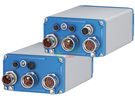
The AKD-N Family of Digital Drives
Standard features 3to 12A EtherCAT,I/O, Local STO 3to 12A EtherCAT,I/O, Local Fieldbus 3to 12A EtherCAT,I/O, Local STO Supply voltage range 55 VDCto800VDC Motion bus onboard. SFD,HIPERFACEDSL,Comcoder,EnDat2.1&2.2,BiSS,HIPERFACE,1Vp-pSin Cosencoders, incremental encoders support onboard. Safe Torque Off (STO) according to IEC 62061 SIL 2onboard. Usewith synchronous servomotors, linear motors, and induction machines. Power section Connection to AKD-C orMKD-Cpowersupplies. DCpowersupply, voltage range 55 VDCto800VDC. Output stage IGBT module with floating current measurement. Integrated safety Appropriate insulation/creepage distances and electrical isolation for safe electrical sep aration, per IEC 61800-5-1, between the power input/motor connections and the signal electronics. Temperature monitoring of the drive and motor. Motor overloadprotection: foldback mechanism SIL 2safe torque off in accordance with IEC 62061 Operation and parameter setting Using the setup software WorkBench for system setup via TCP/IP connected to X18 of the power supply. Full digital control Digital current controller (670 ns) Adjustable digital velocity controller (62.5 µs) Software option position controller (250 µs)
CableRequirements
Forinformationonthechemical,mechanical,andelectricalcharacteristicsofthecables
pleaserefertotheaccessoriesmanualorcontactcustomersupport.
UseKollmorgenhybrid,motor,andfeedbackcablesonly.Youwill losesystemwarranty,if
youusehybrid,motororfeedbackcablesfromamanufacturerotherthanKollmorgen.
Cable length definition
AKD-Cofferstwoseparatestringstoconnectupto8AKD-Ntoeachofthem.Maximum total cable length for each string is 100 m. For system topology information refer to Cabl
Regen circuit
TheAKD-Chasaninternalregenresistor, MKD-C does not offer an internal resistor. An external regen resistor can be connected to X14 on both power supplies. External regen resistors are described in the regional AKD Accessories Manual.
Functional description
Whentheamountofreturned energy builds the bus capacitor voltage up enough the power supply activates the brake chopper to start dumping the returned energy in the regen res istor. 90% of the combined power of all the coupled drives is always available for peak and continuous power.
Switch-off on over voltage
Thedrive that has the lowest switch-off threshold (resulting from tolerances) reports an over-voltage fault if the DC bus threshold is exceeded. The drive power stage is disabled and the load coasts to a stop with the fault message “F501 Bus Over voltage". The fault relay contact (AKD-C: X15/5-6, MKD-C: X15A/1-2) is opened due to this fault
Technical data
Technical data are listed in the installation manuals for AKD-C / MKD-C
LED Codes
Thebuilt-in LED indicates the status of the drive after the 24 V supply for AKD-C is
switched on. If the AKD-C service connection to the PC or to the PAC doesn't work, then
the LEDisthe only waytoget information.
There is a danger of serious personal injury or death by electrical shock or electrical arcing. The built-in LED does not indicate the real voltage level. Always measurethe voltage in the DC buslink at connector X14 at AKD-C respectively X23atMKD-Cand wait until the voltage is below 50 V before handling any component in the decentral servo system
TheLEDdelivers information with three colors (red, green, yellow) and blink frequency. Specialist can analyze the blink frequency, more information to that can be found in the WorkBenchonline help
Switch-On and Switch-Off Behavior
Behavior of “holding brake” function
Drives with an enabled holding brake function have a special timing for switching on and off the output stage. Events that remove the DRV.ACTIVE signal trigger the holding brake to apply. As with all electronic circuits, the general rule applies that there is a possibility of the internal holding brake module failing. Functional safety, for example with hanging load (vertical axes), requires an additional mechanical brake which must be safely operated, for example by a safety control. If velocity drops below threshold CS.VTHRESH or timeout occurs during a stop procedure, the brake is applied. Set parameter MOTOR.BRAKEIMMto1withvertical axes, to apply the motor holding brake immediately after faults or Hardware Disable
Safety function STO
With the functional safe function STO, the drive can be secured on standstill using its
internal electronics so that even when power is being supplied, the drive shaft is protected
against unintentional restart. The chapter “Safe Torque Off (STO)” describes how to use
the STOfunction
Switch-on behavior in standard operation
Thediagram belowillustrates the correct functional sequence for switching the drive on.

Switch-off behavior
TheAKD-C/MKD-C24Vsupplymustremainconstant.HardwareEnableinputdisables all AKD-N powerstages immediately. Configured Digital Inputs and fieldbus commands can beusedtoperformcontrolled stops
Thecontrol functions Stop, Emergency Stop and Emergency Off are defined by IEC 60204. Notes for safety aspects of these functions can be found in ISO 13849 and IEC 62061.
TheparameterDRV.DISMODEmustbesetto2toimplementthedifferentstopcat egories. Consult the WorkBench Online Help for configuring the parameter.
Serious injury could result when a suspended load is not properly blocked. Functional safety, e.g. with hanging load (vertical axes), requires an additional mechanical brake which must besafely operated, for example by a safety control. Addasafemechanical blocking (for instance, a motor-holding brake). Set parameter MOTOR.BRAKEIMMto1withverticalaxes, to apply the motor holding brake immediately after faults or Hardware Disable.
Switch-off behavior using a digital input (controlled stop)
This is a category 2 stop according to IEC 60204. A digital input can be configured to bring
the motor to a controlled stop and then disable the drive and apply the holding brake (if
present). See the WorkBench Online Help for information on configuring Digital Inputs.
Switch-off behavior using the DRV.DIS command
Theenable/disable button in WorkBench issues a drv.dis command internally to the drive.
SeeWorkBenchOnlineHelpforconfiguring inputs and software commands. Sometimes
this enable signal is called "Software Enable" (SW-Enable).
Switch-off behavior using HW Enable input on AKD-C (uncontrolled stop)
This is a category 0 stop according to IEC 60204. The hardware enable input disables the
AKD-Npowerstageimmediately.
If velocity drops below threshold CS.VTHRESH or timeout occurs the motor holding brake is applied. Set parameter MOTOR.BRAKEIMMto1withvertical axes, to apply the motor holding brake immediately after Hardware Disable
Switch-off behavior in the event of a fault
Thebehavior of the drive always depends on the fault type and the setting of a number of
different parameters (DRV.DISMODE, VBUS.UVFTHRESH, CS.VTHRESH,andothers;
see the WorkBenchOnline Help for moredetails).See the Drive Fault and Warning Mes
sages andRemediessection of the WorkBenchOnline Help for a table describing the spe
cific behavior
Switch-off behavior for faults that cause an immediate power stage disable
This is a category 0 stop according to IEC 60204
Switch-off behavior for faults that cause dynamic braking
This is a category 0 stop according to IEC 60204.
Switch-off behavior for faults that cause a controlled stop
This is a category 1 stop according to IEC 60204.
Safe Torque Off (STO)
TheSTOfunctionality of AKD-N with option "DB" or "DF" or "DG" is controlled by the AKD
CorMKD-Csmartpowersupplyviathespecific string, where the AKD-N is connected to.
This STOtopology is called "Global STO" or "String STO".
AKD-Ndrives with option "DS" or "DT" offer an additional connector X6 with a digital STO
Enable input. This STO functionality is called "Local STO". These drive variants cannot be
safety controlled by the global STO functionality.
Global STO, control via AKD-C
Connector X16 ontheAKD-Coffersaccess to all STO signals of the decentral drive system powered bythis AKD-C.ThereisoneSTO-Enableinput andoneSTO-Statusoutput for each DCPowerstring. Theglobal STOfunction is described in the AKD-C Installation Manual. Application examples can be found in the Decentralized System Project Guide. TheglobalSTOfunctionusesthefollowingdevices:AKD-C,AKD-Nwithoutoption "DS/DT", Kollmorgen hybrid connection cable. In case of using an AKD-Nwithoption "DS" or "DT" (local STO input), the global STO Enable signal will have not influence to this specific drive. The local STO-Status of this drive nevertheless is monitored in the string STO-Status
Global STO, control via MKD-C
Connector X16A/B ontheMKD-Coffersaccesstoall STOsignals of the decentral drive
system powered bythis MKD-C.ThereisoneSTOinputandoneSTO-Statusoutputfor
every DCPowerstring.
Theglobal STOfunction is described in the MKD-C Installation Manual.
TheglobalSTOfunctionusesthefollowingdevices:MKD-C,AKD-Nwithoutoption"DS"
or "DT", Kollmorgen hybrid connection string cable.
In case of using AKD-Nwith option "DS" or "DT" (local STO input), the global STO signal
will have no influence to these specific drives.
In case of using more than 8AKD-NwithHardwareRevisonAorBinonestring,youmust
connect a signal buffer to the STO signal.
Maximumdevicenumberperstring:
Hardware Revision A or B: maximum8AKD-N
Hardware Revision A or Bwith signal buffer: maximum 14 AKD-N
Hardware Revision C: maximum14AKD-N
Local STO, control via digital input on AKD-N-DS/DT
Option DS and DT ontheAKD-Nofferlocal STO-Enable functionality. There is one
STO-Enable input on X6andoneSTO-Statusoutput onX3forthedrive. The STO-Status
outputs on X3 are available only with AKD-N drives with option DS or DT
-
Nidec MP700A5 / MP700A5R (700A) high-performance DC thyristor drives
-
Nidec Control Techniques MP350A5 / MP350A5R (350A)
-
Nidec Control Techniques MP210A5 / MP210A5R (210A)
-
Nidec Control Techniques MP155A5 / MP155A5R (155A)
-
Nidec Control Techniques MP105A5 / MP105A5R (105A)
-
Nidec Control Techniques MP75A5 / MP75A5R (75A)
-
Nidec Control Techniques MP25A5 / MP25A5R (25A)
-
Nidec Control Techniques MP1850A4 / MP1850A4R (1850A)
-
Nidec Control Techniques MP1200A4 / MP1200A4R (1200A)
-
Nidec Control Techniques MP900A4 / MP900A4R (900A) Overview
-
ABB PFSA240 Roll DC Supply Unit 3BSE073476R1
-
GE AT868-2-1-1 Flow Meter
-
Nidec Mentor MP825A4 / MP825A4R (825A) High-Power DC Drive
-
Nidec Mentor MP700A4 / MP700A4R (700A) DC Drive
-
Nidec MP550A4 / MP550A4R(550A) high-power DC thyristor drive
-
Nidec Mentor MP420A4 / MP420A4R (420A) High-Power DC Drive
-
Nidec Mentor MP350A4 / MP350A4R (350A) High-Power DC Drive
-
Nidec Mentor MP210A4 / MP210A4R(210A) Industrial DC Drive
-
Nidec Mentor MP155A4 / MP155A4R (155A) Industrial DC Drive
-
Nidec Mentor MP105A4 / MP105A4R (105A) Industrial DC Drive
-
Nidec Mentor MP75A4 / MP75A4R (75A) High-Performance DC Drive
-
NIDEC MP45A4 / MP45A4R – 45Amp 15kW 4 QUADRANT INDUSTRIAL DCDRIVE
-
Nidec MP25A4 / MP25A4R (25A) Industrial Driver
-
Applied Materials (AMAT) 0100-16009 SMIF-Asyst Wide Body Interlock PCB
-
Applied Materials (AMAT) 0100-09134: DIO Fuse Board Assembly
-
Applied Materials (AMAT) 0100-09107: TEOS Gas Interface Board
-
Applied Materials (AMAT) 0100-09094: TEOS Box Heater Control Board
-
Applied Materials (AMAT) 0100-09071 SBC I/O Breakout Board
-
Applied Materials (AMAT) 0100-09010: System Electronics Backplane
-
Applied Materials (AMAT) 0100-09006 Intelligent Interface SBC Module
-
Applied Materials (AMAT) 0100-03920 Analog I/O Interface Board
-
Applied Materials (AMAT) 0100-00511 / 0130-00511: Mainframe I/O Display
-
Applied Materials (AMAT) 0100-00156: Precision Isolation Amplifier Board
-
Applied Materials (AMAT) 0100-00052 High-Performance Communication Interface
-
Autronica Controller rack unit BC-250
-
Autronica Mimic cabinet BUR-200. for maritime installations
-
Autronica Mimic driver BUR-200
-
Autronica Information panel BV-210
-
Autronica Fire brigade panel BU-210
-
Autronica Repeater panel BS-211
-
Autronica Maritime fire alarm control panel BS-200M
-
Autronica Fire alarm control panel BS-200
-
AMAT 0100-00046 AC Current Sense PWB
-
AMAT A0414720 Precision Advanced System Controller
-
AMAT 0010-00017 Precision Semiconductor Process Interface
-
AMAT 01-82889-00 High-Performance Semiconductor Component
-
ABB Sample Gas Cooler SCC-C 23070-0-10232110
-
IBA ibaRackline-PCHD Efficient process analysis with ibaHD-Server
-
IBA ibaRackline-PC CAM Frame-accurate video information with ibaCapture
-
IBA ibaRackline-PC Highly available and reliable
-
IBA Optical Signal Multiplier ibaBM-FOX-i-3o-D
-
IBA Optical Data Distribution System ibaBM-DIS-i-8o
-
IBA Optical Data Concentrator ibaBM-COL-8i-o
-
IBA ibaNet750-BM-D Acquisition via FO
-
IBA ibaW-750 Acquisition via Ethernet
-
IBA ibaPADU-8AI-I Compact Measurement Modules
-
IBA ibaPADU-D-8AI-I Compact Measurement Modules
-
IBA ibaPADU-D-8AI-U Compact Measurement Modules
-
IBA ibaPADU-4-AI-U Compact Measurement Modules
-
IBA ibaPADU-C-8AI Self-Supplied Data Logger
-
IBA ibaBM-ENetIP Bus monitor for EtherNet/IP
-
IBA ibaBM-eCAT Bus monitor for EtherCAT
-
IBA ibaBM-DP Bus monitor for PROFIBUS
-
IBA ibaBM-PN Bus monitor for PROFINET IO
-
IBA ibaMS3xAI-1A Precision AC Current Measurement Module
-
IBA ibaDAQ Intelligent Central Unit
-
IBA ibaPQU-S Power Quality Monitoring System
-
IBA ibaCMU-S Condition Monitoring Unit (CMU)
-
IBA ibaPADU-S-IT-2x16 Modular data acquisition and control system
-
IBA ibaPADU-S-CM Modular data acquisition system
-
IBA ibaM-4AI-IEPE Input module
-
IBA ibaM-4AI-UI Input module
-
IBA ibaM-4AI-150V-AC Input module
-
IBA ibaM-4AI-600V-AC Input module
-
IBA ibaLink-SM-256V High-Density PLC Data Interface
-
IBA ibaLink-SM-64V High-Performance S5/S7 Interface
-
IBA ibaLink-SM-128V-i-2o Synchronous Fiber Optic (ibaNet)
-
IBA ibaLink-SM-128V communication module
-
IBA ibaM-4AI-5A-150A-AC Input module
-
IBA ibaM-FO-2IO Interface module
-
IBA ibaM-COM Communication module
-
IBA ibaM-DAQ Intelligent Processor Module
-
B&R ECNT43-0 MULTI power supply module
-
B&R ECEP128-0 MULTI application memory
-
B&R ECCP60-01 MULTI CPU type B 42 KByte SRAM
-
B&R DI426 digital input module
-
B&R 2DS100.60-1 electronic drum sequencer Absolut encoder
-
B&R 2CP100.60-1 CPU MODULE
-
B&R 2BM100.9 High-performance I/O module
-
AMAT 0190-14928 SCR Power Controller (PVD Reverse Zone)
-
AMAT 0500-01065 300mm Loadlock Interface Interlock Board
-
AMAT 2000-21123 Advanced Vacuum Seal Assembly
-
AMAT 0660-00090 High-Performance Industrial Power Filter
-
AMAT 0240-34077 Centura Endpoint Controller Kit
-
AMAT 0195-10215 High-Precision Pedestal Assembly
-
AMAT 0190-76050 VGA Video Controller VME Module
-
AMAT 0190-75084 High-Performance Communication & Logic Controller
-
AMAT 0190-60287 Precision VME/cPCI Interface Control Module
-
AMAT 0190-53752 DI Water I/O Controller PCB
-
AMAT 0190-37993 DeviceNet Scanner Pro (3U CompactPCI)
-
AMAT 0190-37833 MKS CDN500R-5 EPI 300mm Interface Module
-
AMAT 0190-37771 MKS CDN500R Interlock Control Module
-
AMAT 0190-37616 High-Precision Analog Input/Output Interface
-
AMAT 0190-36787B ISAC CP I/O Block 2 (Top) - Revision B
-
AMAT 0190-36787 ISAC CP I/O Block 2 (Top)
-
AMAT 0190-36511 DIP294 DeviceNet I/O Control Block
-
AMAT 0190-35764 & 0190-35765: Precision Control Interface Duo
-
AMAT 0190-35763 High-Performance Integrated Power Module
-
Applied Materials (AMAT) 0190-34512: 4-Channel DeviceNet Scanner Interface
-
Applied Materials (AMAT) 0190-34282 High-Stability Process Control Module
-
Applied Materials (AMAT) 0190-27707 High-Precision DeviceNet I/O Controller
-
Applied Materials (AMAT) 0190-27072 High-Performance Semiconductor Interface
-
AMAT 0190-24007 CPCI-3720CF Single Board Computer
-
AMAT 0190-23905 Spellman ESC High Voltage Power Supply
-
AMAT 0190-22967 High-Density Analog I/O Control Board
-
AMAT 0190-22543 High-Precision Analog Input/Output Module
-
AMAT 0190-17894 Interlock Module Conductor HART
-
AMAT 0190-17081 2U CompactPCI System Host Processor
-
AMAT 0190-16926 and 0190-16928 Based on Compact PCI
-
AMAT 0190-15915 Intelligent I/O Control Module
-
AMAT 0190-15840 4-Port UPA DeviceNet Interface Module
-
AMAT 0190-15384 Advanced Digital Signal Interface Module
-
AMAT 0190-15384 Advanced Digital Signal Interface Module
-
AMAT 0190-14027 Wafer Flat Finder PCB
-
AMAT 0190-12695 SBS CL7 3U CompactPCI Single Board Computer
-
AMAT 0190-11817 CP3-SER16-TTL 16-Port Serial Interface Card
-
AMAT 0190-11524 CDN500-25 Interlock Module
-
AMAT 0190-07450 CompactPCI 48-Channel Digital I/O Interface Board
Add: High-tech Software Park, Xiamen City, Fujian Province
Mobile: +86-17750019513(WhatsApp)
Email: yy4291644@gmail.com
Website: https://www.abb-sis.com
.jpg)
.jpg)
.jpg)
.jpg)
.jpg)
.jpg)

-
Nidec MP700A5 / MP700A5R (700A) high-performance DC thyristor drives
-
Nidec Control Techniques MP350A5 / MP350A5R (350A)
-
Nidec Control Techniques MP210A5 / MP210A5R (210A)
-
Nidec Control Techniques MP155A5 / MP155A5R (155A)
-
Nidec Control Techniques MP105A5 / MP105A5R (105A)
