

ABB 07KR51-HSB Hot Stand-By functionalities
Presentation
The 07KR51-HSB is based on the basic 50 series central units. This version of 50 series central unit with redundancy firmware can be used in hot stand-by functionalities on CS31. The meaning is that a hot stand-by remote central unit can handle directly all inputs and outputs on CS31 bus if the hot stand-by master shuts down, without any discontinuity on the process. The hot stand-by remote central unit is only a reading of all inputs on the CS31 bus and it executes its own program without any output assignment. The user program in both central units can be different (for example to implement a shutdown sequence). In case of an error in the hot stand by master central unit, the hot stand-by remote central unit will take over within a maximum of 3 cycle times.
General set-up rules
In order to assure this functionality, the architecture must have one 07KR51-HSB central unit configured in master hot stand-by, and one slave 07K51-HSB central unit configured in slave remote hot stand-by.
Each 07KR51-HSB central units incorporate a specific number of binary inputs / outputs. And it is possible, to increase this number of binary or analog inputs / outputs, by addition of different extensions directly connect to the 07KR51-HSB central units.
These extensions are the same that used with standard 40 and 50 series central units. (See references inside technical documentation – 1SBC260400R1001)
It is possible to use decentralized inputs / outputs units via the CS31 twisted pair:
- ICMK14F1 or ICMK14N1 remote units + its own basic extensions
- 07KR51 or 07KT51 basic central units configured in slave mode.
- DC551 remote units + its own basic extensions
It is not possible to use the following function blocks (MT_CS31, MR_CS31, ST_CS31 and SR_CS31) under AC31GRAF programming software, to simplify the communication between the 07KR51-HSB master central unit and basic slave central units.
In order to use the S500 remote units DC551 + its own basic extensions, it is necessary to used specific function blocks in order to configure the inputs /outputs parameters. These function blocks are only available with AC31GRAF programming software.
The cycle time of both the central units, master and slave HSB, have to be set exactly similar for a perfect synchronisation. It is not recommended to load more than 50% of the memory.
The front (see Figure)
1 - Location for the DIN rail
2 - Plate fixture with unit earthing
3 - Lock for DIN rail mounting
4 - Location for external dual connector
5 - Location for the cabling connectors: - of 24 V d.c. output power for the inputs (available only for the remote units with 120 / 230 V a.c. power) - of the inputs
6 - Visualization set for the status of the 8 inputs / 6 outputs
7 - Location of the connector for the connection of input/output extensions
8 - Location of the cabling connectors: - the serial port for programming or communication ASCII / MODBUS® - connector for the central unit power supply cabling - connectors for the outputs cabling
9 - Location of the addressing rotate selectors (see enlargement)
10 - Unit status visualization area: - POWER: power on - RUN: Blinking indicates the valid message received - ERR: On indicates error(s) present and blinking indicates configuration action
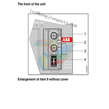
Enlargement of item 9 without cover (see Figure)
1 - Potentiometer whose value is read into the IW62.01 variable by the program (value of 0 to 150 in the program)
2 - Screwdriver for potentiometer adjustment
3 - Potentiometer whose value is read into the IW62.00 variable by the program (value of 0 to 150 in the program) 4 - Central unit program ON/OFF switch
-
Basler Electric SGC-250. Synchronous Generator Controller
-
Basler Electric BE1-50/51 Plug and Play and Retrofit Relays
-
Basler Electric DECS-2100. Digital Excitation Control System
-
Basler Electric DECS-250E, Digital Excitation Control System
-
Basler Electric BE1-700V, Voltage Only Digital Protective Relay
-
Basler Electric DECS-250. Digital Excitation Control System
-
Basler Electric DECS-450. Digital Excitation Control System
-
Basler Electric DECS-150. Digital Excitation Control System
-
Basler Electric Basler Electric ES-49. Temperature Relay
-
Basler Electric ES-81O/U, ES-81O,ES-81U Overfrequency Relay
-
Basler Electric ES-74V, DC Voltage Sensing Relay
-
Basler Electric ES-27/59. Under/Overvoltage Relay
-
Basler Electric ES-27. Undervoltage Relay
-
Basler Electric ES-25. Sync-Check Relay
-
Basler Electric ES-47, ES-47N Phase Sequence Relay
-
Basler Electric ES-37.ES-37/51 Undercurrent Relay
-
Basler Electric ES-32. Reverse Power Relay
-
Basler Electric ES-32. Reverse Power Relay
-
Basler Electric ES-59. Overvoltage Relay
-
Basler Electric ES-55. Power Factor Relay
-
Basler Electric DGC-2020HD, Digital Genset Controller
-
Basler Electric BE1-FLEX, Protection, Automation, and Control System
-
Schneider GUTOR OC0935 Power Factor Sampling Board
-
Schneider GUTOR OC0922 Analog Signal Isolation Board
-
Schneider GUTOR OC0908 Battery Voltage Detection Board
-
Schneider GUTOR OC0947 Temperature / IGBT Sampling Board
-
Schneider GUTOR OP2601 Communication Expansion Board
-
Schneider Electric GUTOR OP2312 bypass control board
-
Schneider Electric GUTOR OP2130 Cooling Fan Monitoring & Control Board
-
Schneider Electric GUTOR OP2010 Battery Test Board / Battery Management Diagnostic Card
-
Schneider Electric GUTOR OP2552 Three-phase Power Connection Board Assembly
-
Schneider Electric GUTOR OP1922A Parallel Control Board / Load-Sharing Synchronization Module
-
Schneider Electric GUTOR OP6290B Inverter Feedback Acquisition Board / Signal Scaling Module
-
Schneider GUTOR OP6280 Basic Signal Board
-
Schneider Electric GUTOR OP2456 / OP2456B Main control board
-
Schneider Electric GUTOR OP2452 Power Plug-in Panel
-
Schneider Electric GUTOR OP2450 Parallel Communication Board
-
Schneider Electric GUTOR OP2406 Interface Fuse Monitoring Board
-
Schneider Electric GUTOR OC0919 High-Power Semiconductor Module
-
Schneider Electric GUTOR OP6281A System Logic Interface Board
-
Schneider Electric GUTOR OP6285A Power Signal Acquisition Board
-
Schneider Electric GUTOR OP2438 Fan Monitor & Drive Protection Board
-
Schneider Electric GUTOR OP2446 Main Control CPU Board
-
ROLLS-ROYCE CE05-00 Steering Gear Control Module
-
ROLLS-ROYCE MARINE AS-BRATTVAAG WRC1021A CONTROLLER CARD
-
ROLLS ROYCE DECK MACHINERY MPC-300-A7029099 TERMINAL CONTROLLER UNIT
-
ROLLS-ROYCE HELICON THRUSTER CONTROL PANEL LF90S-01-06
-
Rolls-Royce PCC1030C Panel Controller Card
-
Rolls-Royce RRDIO15 Remote Digital Input/Output Module
-
Rolls-Royce TDI-11 Pitch & Direction Indicator Module
-
Rolls-Royce CCN 01 CANman Controller Network Module
-
Rolls-Royce SLIO 01 CANman Controller Network Module
-
Rolls-Royce MPC-210 Winch & Propulsion Control Module
-
Rolls-Royce MTI-144 Engine Control Module
-
Rolls-Royce Tenfjord FB10-002 Steering Gear Module (E-4500-40-1)
-
ROLLS ROYCE MARINE AS CIRCUIT BOARD (PCB) RRAI016
-
Rolls-Royce Marine AS PIP6-1 Marine Controller
-
ROLLS-ROYCE MPC-300 STARTER CONTROL UNIT A7029099
-
Rolls-Royce Data Respons MPCF1-10.4" Maritime Panel Computer
-
ROLLS-ROYCE MARINE OLC-40009 PCB CARD
-
Rolls-Royce Marine Brattvaag WRC1021B Controller Board
-
ROLLS-ROYCE CCN 01 & ROLLS-ROYCE SLIO 02 CANMAN CONTROLLER NETWORK
-
ROLLS-ROYCE ATC-3-A7033172 AQUAMASTER TURNING CONTROLLER
-
ROLLS-ROYCE POSCON V.3 JOYSTICK MODULE 6459
-
Rolls-Royce Marine 389-496-00 Joystick Remote Control Panel 6799-W, 389-996-00
-
Rolls-Royce data respons 10.4'' Panel Computer 98H010A0000I/R10I53S
-
Rolls-Royce H1127.0101 Marine Controller 000068308
-
Rolls-Royce CU40-0106-50 Steering Gear Control Panel
-
Beckhoff Polaris CP7011-1002-0010 operator operator HMI display 30.5 cm
-
Beckhoff AM8052-0JH1-0000 Servomotor 10.7 Nm (M0), F5 (104 mm)
-
Beckhoff AM8052-0JH1-0000 Servomotor 10.7 Nm (M0), F5 (104 mm)
-
Beckhoff BX5100-0000 CANopen Bus Terminal Controller
-
Beckhoff CX9020-0115 PLC Module CX90200115
-
Beckhoff module EJ7211-0010 EtherCAT plug-in module
-
BECKHOFF AX5203-0000 Servo Driver
-
BECKHOFF CP6201-0001-0020 24VDC UNMP
-
Beckhoff CX5120-0135 Embedded PC CPU Module
-
BECKHOFF C5240-0020/000224115 Plc Module
-
Beckhoff CP2918-0000 PanelCP29xx-0000 | Multi-touch built-in Control Panel with DVI/USB Extended interface
-
Beckhoff CX2020-0122 Embedded PC Controller
-
Beckhoff C6640-0040 Control Cabinet Industrial PC 7-Slot
-
BECKHOFF CONTROL CABINET INDUSTRIAL PC - C6930-1062-0050
-
Beckhoff Automation EtherCAT Terminal EK1100 EK1122
-
Beckhoff CP6533-0001-0060 IPC
-
Beckhoff EK9500 | EtherNet/IP™ Bus Coupler
-
Beckhoff CP6202-1047-0050 - An industrial-grade embedded panel computer.
-
Beckhoff C6650-0040 Industrial PC
-
BECKHOFF CX5230-0185 / 000119805 PLC Module
-
Beckhoff EL3773 PLC Module
-
BECKHOFF EL4732 (PKG OF 10) NSMP
-
Beckhoff CP6202-0001-0010 Economy Built-In Panel
-
Beckhoff AX5206-0000-0202 Digital Compact Servo Drives 2-channel
-
Beckhoff Panel PC CP6606-0001-0020 7-inch Economy Panel PC
-
Beckhoff CPU basic module CX2020-0155 + power supply module CX2100-0004
-
Beckhoff CP2913-000 Multi-Touch Display
-
Beckhoff CP6500-1012-0060 14250369 Control Cabinet
-
Beckhoff CP7902-0001-0000 Economy Control Panel with DVI/USB Extended interface
-
Beckhoff C6920-0010 Core Duo 2.00 GHz
-
BECKHOFF C3640-0050 Build-in Industrial PCs
-
Beckhoff KL6023-0000 KL6023 EnOcean Wireless-Adapter
-
Kollmorgen AKM54G-ANC2DB00 servo motor
-
Kollmorgen S200 Series S20350-VTS SERVO DRIVE
-
KOLLMORGEN AKD-P00606-NBCC-I000 SERVO DRIVE
-
Kollmorgen MV65WKS-CE310/22PB Servo Drive Control Module
-
Kollmorgen S20360-VTS-021 Servo Drive
-
KOLLMORGEN CR06550 High-precision digital servo amplifier
-
KOLLMORGEN DBL5N01050-03S-VV0-S40 Phase AC Synchronous Brushless Servo Motor
-
KOLLMORGEN S70301-NANANA-024 SERVO DRIVE
-
Kollmorgen S20360-VTS S200 Series Servo Drive
-
Kollmorgen RBE-03011-A00 Brushless Frameless Servo Motor
-
KOLLMORGEN AKD-T00306-NBAN-0000 INPUT SERVO DRIVE
-
KOLLMORGEN S700 Servo Controller S70302-NANANA
-
Kollmorgen AKD-P00607-NBEC-0000 400/480VAC 4.40KVA Servo Drive.
-
KOLLMORGEN S70102-NANANA SERVO DRIVE
-
KOLLMORGEN AKM21E-ANSNEH02 PM Servo Motor & PRD-AMPE25EB-00 Servo Drive Array
-
KollMorgen SC1R06260 Servo Drive 1.4/2.2 KVA 115230 Vac
-
Kollmorgen AKD-P00306-NBAN-0000 Servo Drive
-
Kollmorgen TTB2-2042-3052-A DC Motor Industrial Drive 5.5A 185 oz/inIntegrated safety
-
KOLLMORGEN SERVOSTAR 610-AS SERVO AMPLIFIER_SERVOSTAR610AS_S61001
-
KOLLMORGEN Seidel 60WKS-CE240/26PB 26A Servo Drive Module Control 60WKS-M240/26
-
KOLLMORGEN PRD-0016400P-10 & PRD-0016600D-30 Axis Control System Modules
-
KOLLMORGEN Seidel DBL5N01700-03S-000-S40 Servo Motor
-
HIRSCHMANN RS30-0802O6O6SDAP RAIL SWITCH
-
Hirschmann RS20-1600M2T1SDAEHH03.1.02 Rail Switch
-
Hirschmann RSPM20-4T14T1EV9HHS999.9.99 Managed Ethernet Switch
-
Hirschmann BELDEN RS40-0009CCCCSDAPHH09.0.14 / RS400009CCCCSDAPHH09014
-
Hirschmann RS40 Rail Switch RS40-0009CCCCSDAE
-
Hirschmann BELDEN RS30-0802T1T1SDAP / RS300802T1T1SDAP Fully Managed Layer 2 Compact Rail Switch
Add: High-tech Software Park, Xiamen City, Fujian Province
Mobile: +86-17750019513(WhatsApp)
Email: yy4291644@gmail.com
Website: https://www.abb-sis.com
.jpg)
.jpg)
.jpg)
.jpg)
.jpg)
.jpg)

-
Basler Electric SGC-250. Synchronous Generator Controller
-
Basler Electric BE1-50/51 Plug and Play and Retrofit Relays
-
Basler Electric DECS-2100. Digital Excitation Control System
-
Basler Electric DECS-250E, Digital Excitation Control System
-
Basler Electric BE1-700V, Voltage Only Digital Protective Relay
