

Basler Electric DECS-200 Digital Excitation Control System
Basler Electric DECS-200 Digital Excitation Control System
This instruction manual provides information about the operation and installation of the DECS-200 Digital
Excitation Control System. To accomplish this, the following information is provided:
• General Information and Specifications
• Controls and Indicators
• Functional Description
• Installation
• Maintenance
INTRODUCTION
The Basler Digital Excitation Control System (DECS-200) is a microprocessor-based control device
intended for generator power management. Programmability of system parameters and regulation
settings enables the DECS-200 to be used in a wide range of applications and provides greater flexibility
in excitation system optimization. The DECS-200 can accommodate generator exciter field requirements
up to 15 Adc continuously in 32. 63. or 125 Vdc applications with one model.
FEATURES
DECS-200 units have the following features and capabilities.
Functions
• Four control modes
o Automatic voltage regulation (AVR)
o Manual or field current regulation (FCR)
o Power factor (PF)
o Reactive power (var)
• Soft start buildup with an adjustable ramp in AVR and FCR control modes
• One adjustment range or pre-position setpoint for each control mode
• Overexcitation limiting (OEL) and underexcitation limiting (UEL) in AVR, var and PF control modes
• Twenty stability selections
• Underfrequency compensation or volts per hertz ratio limiter
• Autotracking between operating modes and between DECS-200 units (optional)
• Automatic transfer to a backup DECS-200 unit (optional)
• Eight generator protection features
o Field overvoltage
o Field overcurrent
o Generator overvoltage
o Generator undervoltage
o Watchdog timer
o Loss of sensing
o Exciter diode monitor (EDM)
o Loss of field
• Generator paralleling with reactive droop compensation and reactive differential compensation
• Data logging and event recording
Inputs and Outputs
• Single-phase rms bus voltage sensing
• Single-phase or three-phase rms generator voltage sensing
• Single-phase generator current sensing (1 or 5 amperes, nominal)
• Analog inputs (±10 Vdc and 4 to 20 mAdc) provide proportional, remote control of the setpoint
• Eleven PLC-compatible contact sensing inputs for system interface
• Separate ac and dc power inputs accommodate redundant operating power sources
• Pulse-width modulated output power stage rated at a maximum of 15 amperes, continuous
• Five output relays for system control or annunciation
o Three programmable output relays
o Two fixed-function output relays
HMI Interface
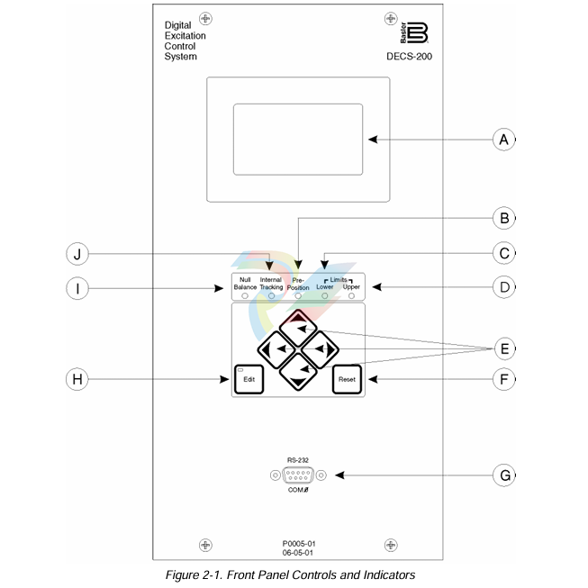
• Front panel HMI includes pushbutton controls, LED indicators and a backlit, liquid crystal display
(LCD)
• BESTCOMS™ Windows® based software provides easy, fast and accurate setup and control
Three communication ports
o Front RS-232 port for communication with a PC using BESTCOMS software
o Right-side panel RS-232 port for dedicated communication with a redundant DECS-200
o RS-485 communication port for communication with a remote terminal
• Modbus protocol for the RS-485 port allows communication at distances of up to 1.200 meters
(3.937 feet)
Introduction
In the typical application shown in Figure 1-1. the DECS-200 controls the exciter field of a synchronous
generator. Front panel controls, indicators, and serial communication ports using PC software make the
system easy to operate locally or from remote locations. DECS-200 operation, settings, and safety setup
procedures in this manual should be studied before implementing your application. For detailed
application assistance, contact Basler Electric or your local sales representative.
Operating Power
Operating power for the pulse-width modulated (PWM) excitation output is typically obtained from the
generator output through a power transformer. Alternately, operating power can be supplied from a
permanent magnet generator (PMG).
During DECS-200 power-up, an optional ICRM (Inrush Current Reduction Module) prevents damage to
the DECS-200 by limiting inrush current to a safe level. For more information, refer to Section 4.
Installation.
Control Power
If power supply option C (120/125 Vac/Vdc) is selected, a redundant power source can be used with the
DECS-200. (See Figure 1-1.) In this configuration, if one of the two sources fails, the other source will
continue to supply DECS-200 operating power. If power supply option L (24/48 Vdc) is selected, no
redundant power source is available.
Sensing
The DECS-200 senses generator voltage and current through voltage and current transformers. Field
voltage and field current values are sensed internally.
Excitation Limiters
Integrated overexcitation and underexcitation limiters (OEL and UEL) are available for both on-line and
off-line protection.
External Tracking and Transfer Between DECS-200 Units (Optional)
For critical applications, a second DECS-200 can provide backup excitation control. The DECS-200
allows for excitation system redundancy by providing external tracking and transfer provisions between
DECS-200 units. The secondary DECS-200 operating modes can be programmed to track the primary
DECS-200 operating mode. Proper, redundant excitation system design allows for removal of the failed
system. Periodic testing of the backup system must be performed to ensure that it is operational and can
be put into service without warning.
Internal Tracking Between DECS-200 Operating Modes
In applications using a single DECS-200. the DECS-200 can be programmed so that the inactive
operating modes track the active operating mode. Operating modes include AVR, FCR, PF, and var. If
the excitation system is normally operating on-line in Internal mode and a loss of sensing occurs, the
DECS-200 could be transferred to manual (FCR) mode where the loss of sensing has no impact on the
exciter's ability to maintain proper excitation levels. While performing routine testing of the DECS-200 in
backup mode, the internal tracking feature allows a transfer to an inactive mode that will result in no
disturbance to the system.
Communication With a PC
Communication between the DECS-200 (front panel RS-232 port) and a PC is possible through
BESTCOMS software. BESTCOMS enables fast and easy programming of setpoints and ranges and
allows for step changes to facilitate proper stability settings. BESTCOMS also provides easy start and
stop control and operator adjustment of the excitation system with real-time metering. The software
catalog number is BESTCOMS-DECS200. BESTCOMS is provided with the DECS-200 as part of the
software/manual package.
Sample Style Number
The style number identification chart (Figure 1-2) defines the electrical characteristics and operational
features included in the DECS-200. For example, if the style number were DECS-200-1L, the device
would have the following characteristics and features.
DECS-200 -- Digital Excitation Control System
1 --- Internal autotracking/transfer
L --- 24/48 Vdc control power supply
SPECIFICATIONS
DECS-200 electrical and physical characteristics are listed in the following paragraphs.
Control Power
Input Voltage
DC Input: 16 to 60 Vdc (style XL) or 90 to 150 Vdc (style XC)
AC Input: 85 to 132 Vac, 50/60 Hz (style XC only)
Note: Isolation transformer for ac input is required when dual control
power sources are used.
Burden
DC Input: 30 W
AC Input: 50 VA
Terminals
DC Input: B7 (+), B8 (–)
AC Input: B9 (L), B10 (N) (style XC only)
Operating Power
To achieve the proper DECS-200 output voltage, the appropriate operating power input voltage must be
provided.
32 Vdc PWM Output
Nominal: 60 Vac
Operating Range: 56 to 70 Vac, ±10%
Frequency Range: 50 to 500 Hz
Configuration: 1-phase or 3-phase
Burden: 780 VA
63 Vdc PWM Output
Nominal: 120 Vac
Operating Range: 100 to 139 Vac, ±10%
Frequency Range: 50 to 500 Hz
Configuration: 1-phase or 3-phase
Burden: 1.570 VA
125 Vdc PWM Output
Nominal: 240 Vac
Operating Range: 190 to 277 Vac, ±10%
Frequency Range: 50 to 500 Hz
Configuration: 1-phase or 3-phase
Burden: 3.070 VA
Voltage Buildup
From a minimum of 3 Vac
Terminals
C2 (A-phase), C3 (B-phase), C4 (C-phase)
Burden: <1 VA per phase
Terminals: A1. A2. A3
50 Hertz Sensing
Range 1: 100 Vac (85 to 127 Vac)
Range 2: 200 Vac (170 to 254 Vac)
Range 3: 400 Vac (340 to 508 Vac)
Range 4: 500 Vac (425 to 625 Vac)
60 Hertz Sensing
Range 1: 120 Vac (94 to 153 Vac)
Range 2: 240 Vac (187 to 305 Vac)
Range 3: 400 Vac (374 to 600 Vac)
Range 4: 600 Vac (510 to 660 Vac)
Generator Current Sensing
Type: Two ranges, two channels
Frequency: 50/60 Hz
Ranges: 1 A or 5 A nominal, continuous
Burden: <1 VA per phase
Terminals
1 A Sensing: B1. B3 (phase B, metering, var/PF, UEL)
B4. B6 (phase B, crosscurrent compensation)
5 A Sensing: B2. B3 (phase B, metering, var/PF, UEL)
B5. B6 (phase B, crosscurrent compensation)
Bus Voltage Sensing
Type: 1-phase, 4 ranges,
Burden: <1 VA
Sensing Ranges: Identical to generator voltage sensing
Terminals: A4. A5
Accessory Inputs
Current Input
Range: 4 to 20 mAdc
Terminals: A6 (+), A7 (–)
Voltage Input
Range: –10 to +10 Vdc
Terminals: A9 (+), A10 (–)
Communication Ports
Interface
RS-232: Full duplex
RS-485: Half duplex
Connections
Com 0: Front panel DB-9 connector
Com 1: Right-side panel DB-9 connector
Com 2: Left-side panel screw terminals (A43. A44. A45)
Parameters
Baud: 1200 to 19200
Data Bits: 8
Parity: None
Stop Bits: 1 (Com 0. Com 1) or 2 (Com 2)
Contact Inputs
Type: Dry contact; accept PLC open-collector outputs
Interrogation Voltage: 12 Vdc
Terminal Assignments
Start: A21. A22
Stop: A23. A24
Auto (AVR): A25. A26
Manual (FCR): A27. A28
Raise: A29. A30
Lower: A31. A32
Pre-Position: A33. A34
Unit/Parallel (52L/M): A35. A36
Var/PF (52J/K): A37. A38
Secondary Enable: A39. A40
Alarm Reset: A41. A42
Contact Outputs
Make and Break Ratings (Resistive)
24 Vdc: 7.0 A
48 Vdc: 0.7 A
125 Vdc: 0.2 A
120/240 Vac: 7.0 A
Carry Ratings (Resistive)
24/48/125 Vdc: 7.0 A
120/240 Vac: 7.0 A
Terminal Assignments
Start/Stop (ON, OF): A11. A12
Watchdog (WTCHD): A13. A14
Relay 1 (RLY1): A15. A16
Relay 2 (RLY2): A17. A18
Relay 3 (RLY3): A19. A20
Field Output
Continuous Output Rating
60 Vac Input: 32 Vdc, 15 Adc
120 Vac Input: 63 Vdc, 15 Adc
240 Vac Input: 125 Vdc, 15 Adc
10 Second Forcing Output Rating
60 Vac Input: 50 Vdc, 30 Adc
120 Vac Input: 100 Vdc, 30 Adc
240 Vac Input: 200 Vdc, 30 Adc
Minimum Field Resistance
32 Vdc Application: 2.13 Ω
63 Vdc Application: 4.2 Ω
125 Vdc Application: 8.3 Ω
Regulation
AVR Operating Mode
Accuracy: ±0.25% over load range at rated PF and constant generator frequency
Steady State Stability: ±0.1% at constant load and generator frequency
Temperature Drift: ±0.5% for a 0 to 50°C change
V/Hz Characteristic: Slope from 0 to 3 PU is adjust-able in 0.1 PU increments. Voltage
regulation error is within ±2.0% of the nominal voltage.
Response Time: <1 cycle
-
Beckhoff CX2500-B310 | Fieldbus slave module PROFIBUS for CX20xx, CX52x0. CX53x0. CX56x0
-
Beckhoff CX2500-0070 | USB 3.0 module for CX20xx, CX52xx, CX53x0. CX56x0
-
Beckhoff CX2500-0062 | 2.5 Gbit Ethernet module for CX20xx, CX52x0. CX53x0. CX56x0
-
Beckhoff CX2500-1061 | Power over Ethernet module for CX20xx, CX52x0. CX53x0. CX56x0
-
Beckhoff CX2500-1060 | Ethernet module for CX20xx, CX52x0. CX53x0. CX56x0
-
Beckhoff CX2500-0031 | Serial Interface RS485/RS422
-
Beckhoff CX2500-0030 | Serial Interface RS232 for CX20xx, CX52x0. CX53x0. CX56x0
-
Beckhoff CX5230-0195 CPU module
-
Beckhoff CX5230-0190 CPU module
-
Beckhoff CX5230-0175 CPU module,
-
Beckhoff CX5230-0170 CPU module
-
Beckhoff CX5230-0100 CPU module, no operating system, no TwinCAT
-
Beckhoff CU8130-0240 | UPS modul, battery-backed
-
Beckhoff CU8130-0120 | UPS module, battery-backed
-
Beckhoff CU8110-0120 | UPS module, capacitive
-
Beckhoff CU8110-0060 | UPS module, capacitive
-
Beckhoff CX5130-0195 CPU module
-
Beckhoff CX5130-0190 CPU module
-
Beckhoff CX5130-0185 CPU module
-
Beckhoff CX5130-0170 CPU module
-
Beckhoff CX5130-0163 CPU module, Microsoft Windows 10 IoT Enterprise 2019 LTSC, 32 bit
-
Beckhoff CX5130-0162 CPU module
-
Beckhoff CX5130-0161 CPU module
-
Beckhoff CX5130-0160 CPU module
-
Beckhoff CX5130-0155 CPU module
-
Beckhoff CX5130-0150 CPU module
-
Beckhoff CX5130-0143 CPU module
-
Beckhoff CX5130-0142 CPU module
-
Beckhoff CX5130-0140 CPU module
-
Beckhoff CX5130-0135 CPU module
-
Beckhoff CX5130-0130 CPU module
-
Beckhoff CX5130-0125 CPU module
-
Beckhoff CX5130-0123 CPU module
-
Beckhoff CX5130-0122 CPU module
-
Beckhoff CX5130-0121 CPU module
-
Beckhoff CX5130-0115 CPU module,
-
Beckhoff CX5130-0113 CPU module
-
Beckhoff CX5130-0112 CPU module
-
Beckhoff CX5130-0111 CPU module
-
Beckhoff CX5130-0110 CPU module, Microsoft Windows Embedded Compact 7. no TwinCAT
-
Beckhoff CX5130-0100 CPU module, no operating system, no TwinCAT
-
DEIF FAS-113DG Synchronisation & circuit breaker closing
-
DEIF FAS-115DG Synchronisation & circuit breaker closing
-
DEIF HAS-111DG Synchronisation & circuit breaker closing
-
DEIF LSU-122DG Load sharing, paralleling & operation
-
DEIF LSU-114DG Load sharing, paralleling & operation
-
DEIF LSU-113DG Load sharing, paralleling & operation
-
DEIF LSU-112DG Load sharing, paralleling & operation
-
DEIF RMF-112D Frequency relay
-
DEIF RMC-142D Current relay
-
DEIF RMC-132D Current relay
-
DEIF RMC-131D Current relay
-
DEIF RMC-122D Current relay
-
DEIF RMC-121D Current relay
-
DEIF RMC-111D Current relay
-
DEIF MVR-V211 Busbar Protection
-
DEIF MVR-T257 Transformer Differential Protection
-
DEIF MVR-T256 Transformer Differential Protection
-
DEIF MVR-T216 Transformer Differential Protection
-
DEIF MVR-T215 Transformer Protection
-
DEIF MVR-M257 Motor Differential Protection
-
DEIF MVR-M255 Motor Protection
-
DEIF MVR-M215 Motor Protection
-
DEIF MVR-M210 Motor Protection
-
DEIF MVR-G257 Generator Differential Protection
-
DEIF MVR-G215 Generator Protection
-
DEIF MVR-F255 Directional Feeder Protection
-
DEIF MVR-F215 Directional Feeder Protection
-
DEIF MVR-F210 Feeder Protection
-
DEIF MVR-F205 Directional Feeder Protection
-
DEIF MVR-F201 Basic Feeder Protection
-
DEIF MVR-200 series Medium Voltage Relay
-
DEIF MDR-2 Multi-differential relay
-
DEIF LMR-122D Loss of mains relay
-
DEIF LMR-111D Loss of mains relay
-
DEIF APU-4 Advanced G59 and G99 protection unit
-
DEIF iE 650 PLC - The most robust programmable automation controller available
-
DEIF iE 350 PLC - Programmable Automation PLC Controller
-
DEIF iE 250 PLC Versatile and modular intelligent energy PLC controller
-
DEIF PPM-3 EDG Protection and Power Management
-
DEIF AGC 3X 4198000234E AUTOMATIC GENSET CONTROLLER
-
SAUTER ASF123 Damper actuator with spring return
-
SAUTER ASF122 Damper actuator with spring return
-
SAUTER ASF113F122 Damper actuator with spring return
-
SAUTER ASF113F120 Damper actuator with spring return
-
SAUTER ASF112F122 Damper actuator with spring return
-
SAUTER ASF112F120 Damper actuator with spring return
-
SAUTER ASM 124/134 series - ASM134F130 Damper actuator
-
SAUTER ASM 124/134 series - ASM134SF132 Damper actuator
-
SAUTER ASM 124/134 series - ASM124SF132 Damper actuator
-
SAUTER ASM 124/134 series - ASM124F122 Damper actuator
-
SAUTER ASM 124/134 series - ASM124F120 Damper actuator
-
SAUTER Valve actuator ASM 105S/115S series ASM115SF152
-
SAUTER Valve actuator ASM 105S/115S series ASM105SF152
-
SAUTER Valve actuator ASM 105S/115S series ASM115SF132
-
SAUTER Valve actuator ASM 105/115 series ASM105SF132
-
SAUTER Valve actuator ASM 105/115 series ASM115F122
-
SAUTER Valve actuator ASM 105/115 series ASM115F120
-
SAUTER Valve actuator ASM 105/115 series ASM105F122
-
SAUTER Valve actuator ASM 105/115 series ASM105F120
-
SAUTER Valve actuator ASM 105/115 series ASM105F10
-
SAUTER AKF113S Rotating actuator AKF 112/113 series
-
SAUTER AKF113F122 Rotating actuator AKF 112/113 series
-
SAUTER AKF113F120 Rotating actuator AKF 112/113 series
-
SAUTER AKF112F122 Rotating actuator AKF 112/113 series
-
SAUTER AKF112F120 Rotating actuator AKF 112/113 series
-
SAUTER AKM115SAF332: Smart Actuator for ball valve, BACnet/IP
-
SAUTER AKM115SAF232 Rotating Actuator AKM 115SA Smart Actuator
-
SAUTER AKM115SF152 Rotating Actuator AKM 105S/115S Series
-
SAUTER AKM115SF132 Rotating Actuator AKM 105S/115S Series
-
SAUTER AKM105SF132 Rotating Actuator AKM 105S/115S Series
-
SAUTER AKM115F122 Rotating actuator AKM 105/115 series
-
SAUTER Rotating actuator AKM 105/115 series AKM115F120
-
SAUTER Rotating actuator AKM 105/115 series AKM105F122
-
SAUTER Rotating actuator AKM 105/115 series AKM105F120
-
SAUTER Continuous actuator for unit valves, with stroke AXS215S
-
SAUTER Linear valve actuator AXT/AXS series AXT211
-
SAUTER Linear valve actuator AXT/AXS series AXT201
-
SAUTER Linear valve actuator AXM/AXF series AXF217S
-
SAUTER Linear valve actuator AXM/AXF series AXM217S
-
SAUTER AXM217SF404 is an electric actuator for unit valves.
-
SAUTER AXM217SF402 is an electric actuator for unit valves.
-
SAUTER Linear valve actuator AXM/AXF series AXM217
-
SAUTER Linear valve actuator AVF 124/125 series AVF125S
-
SAUTER Linear valve actuator AVF 124/125 series AVF124S
-
SAUTER AVM322S-R Linear valve actuator AVM 234S series
-
SAUTER AVM322-R Linear valve actuator AVM 234S series
-
SAUTER AVM322SF132 Linear valve actuator AVM 234S series

Add: High-tech Software Park, Xiamen City, Fujian Province
Mobile: +86-17750019513(WhatsApp)
Email: yy4291644@gmail.com
Website: https://www.abb-sis.com



-
Beckhoff CX2500-B310 | Fieldbus slave module PROFIBUS for CX20xx, CX52x0. CX53x0. CX56x0
-
Beckhoff CX2500-0070 | USB 3.0 module for CX20xx, CX52xx, CX53x0. CX56x0
-
Beckhoff CX2500-0062 | 2.5 Gbit Ethernet module for CX20xx, CX52x0. CX53x0. CX56x0
-
Beckhoff CX2500-1061 | Power over Ethernet module for CX20xx, CX52x0. CX53x0. CX56x0
-
Beckhoff CX2500-1060 | Ethernet module for CX20xx, CX52x0. CX53x0. CX56x0
