

Woodward High Output Digital Valve Positioner (DVP) DVP5000/DVP10000/DVP12000
DVP5000/DVP10000/DVP12000
The fan L10 life is rated at 30.000 hours @ 40C. To extend fan life, the DVP switches fan speed at
several internally sensed temperatures to provide optimum balance between cooling and fan life.
Woodward recommends fan assembly replacement every five years of operation.
The fan assembly orderable part number is 8926-1045SPR.
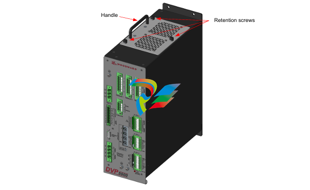
The following procedure is used to replace the fan assembly for the DVP; see Figure 2-5.
Place the actuator into a safe state.
Ensure that input power is removed from the driver.
Unscrew the 3 retention screws. Using the handle, remove the fan assembly from the DVP.
Place the new fan assembly into the connector; tighten the three retention screws.
Apply power to the DVP and ensure the fan alarms are off.
3.1 Power Supply Inputs
The DVP is designed with redundant power supply inputs. These inputs share a common ground and are
isolated from chassis ground. This option allows for redundancy in wiring, connectors, and power sources if
the power sources share a common ground. If one of the inputs is lost, drops low, or experiences temporary
power loss, the other power input will take over without being affected by the first input. The user is provided
four terminals—two plus and two minus. The DVP requires a power supply capable of the specified voltages
and current levels. Please see Table 3-1 for power and fusing information necessary for safe and reliable
operation of the DVP.
3.1.1. Inrush Limiting
The DVP has current inrush limiting built into the design. Power to the CPU occurs rapidly after power
application, but the internal bulk storage capacitors take about eight seconds to fully charge. Inverter
activation is prevented by software until the inrush time has expired. This inrush sequence occurs after
BOTH input power is applied AND EXTERNAL SHUTDOWN input is energized.
3.2 Power Wiring
3.2.1. Recommended Minimum Input Protection:
DVP5000: 15A time delay fuse or 15A breaker
DVP10000 and DVP12000: 30A time delay fuse or 35A breaker (Ambient temperature -40oC to +70oC)
DVP12000: 40A time delay fuse or 45A breaker (Ambient temperature -40oC to +55oC)
High input current transients can be drawn during rapid load movement. The above recommendations
include the transient nature of the electrically driven actuator system. The DVP is not equipped with an
input power switch or breaker. Correct sizing depends on factors such as cable sizing, environment, and
local regulatory requirements. It is recommended that a safety input power switch be provided for
installation and servicing.
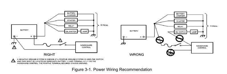
Proper input power wiring to the DVP is crucial to its operation. A circuit breaker meeting the power
supply requirement may be used for this purpose. It is important that proper wiring be applied during
system installation to avoid an unwanted power trip or ground loop. Figure 3-1 illustrates the correct and
incorrect power cable wiring.
3.2.2 Recommendations for Dual and Simplex Power Wiring
The DVP is provided with power terminals suitable for the required voltage and current level. Two positive
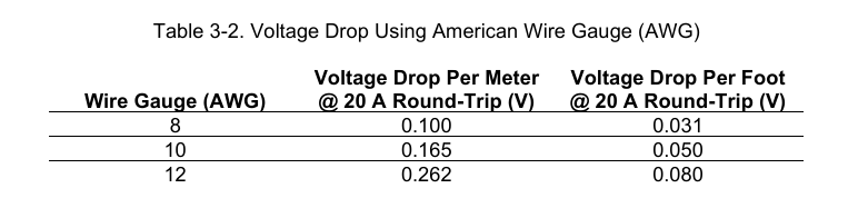
and two negative pins are each sized for 8 AWG wire for the DVP5000 and DVP10000. The DVP12000
can accommodate up to 6 AWG wire.
Provision for separate redundant power supplies is provided by dual DC inputs. Each of the inputs is
diode isolated from the main input bus. If one of the supplies is lost, the other input will take over and the
DVP will continue to operate normally. The loss of the input will be annunciated as an alarm.
Woodward recommends that you take advantage of the dual input power wiring configuration; however,
the inputs can be tied together for use with a single power supply.
If a single power source is used to supply power to the DVP, jumpers should be used to apply power to
both sets of input power terminals. The purpose of these jumpers is to ensure that the power supplied
from the source is distributed equally to the two DVP inputs. This minimizes the power dissipated in each
of the DVP input diodes for reduced heat load and improved reliability. When using the jumpers, insert the
positive (+) power input lead from the power source into either the #1 or #3 positions, and the negative (-)
lead into either the #2 or #4 positions as shown in Figure 3-2a.
Some newer versions of the DVP may include power input plugs with jumpers to connect the two positive
and two negative terminals.
In installations where separate dual power sources are connected to the DVP, as shown in Figure 3-2b,
the jumpers are not required.
-
Beckhoff CX2500-B310 | Fieldbus slave module PROFIBUS for CX20xx, CX52x0. CX53x0. CX56x0
-
Beckhoff CX2500-0070 | USB 3.0 module for CX20xx, CX52xx, CX53x0. CX56x0
-
Beckhoff CX2500-0062 | 2.5 Gbit Ethernet module for CX20xx, CX52x0. CX53x0. CX56x0
-
Beckhoff CX2500-1061 | Power over Ethernet module for CX20xx, CX52x0. CX53x0. CX56x0
-
Beckhoff CX2500-1060 | Ethernet module for CX20xx, CX52x0. CX53x0. CX56x0
-
Beckhoff CX2500-0031 | Serial Interface RS485/RS422
-
Beckhoff CX2500-0030 | Serial Interface RS232 for CX20xx, CX52x0. CX53x0. CX56x0
-
Beckhoff CX5230-0195 CPU module
-
Beckhoff CX5230-0190 CPU module
-
Beckhoff CX5230-0175 CPU module,
-
Beckhoff CX5230-0170 CPU module
-
Beckhoff CX5230-0100 CPU module, no operating system, no TwinCAT
-
Beckhoff CU8130-0240 | UPS modul, battery-backed
-
Beckhoff CU8130-0120 | UPS module, battery-backed
-
Beckhoff CU8110-0120 | UPS module, capacitive
-
Beckhoff CU8110-0060 | UPS module, capacitive
-
Beckhoff CX5130-0195 CPU module
-
Beckhoff CX5130-0190 CPU module
-
Beckhoff CX5130-0185 CPU module
-
Beckhoff CX5130-0170 CPU module
-
Beckhoff CX5130-0163 CPU module, Microsoft Windows 10 IoT Enterprise 2019 LTSC, 32 bit
-
Beckhoff CX5130-0162 CPU module
-
Beckhoff CX5130-0161 CPU module
-
Beckhoff CX5130-0160 CPU module
-
Beckhoff CX5130-0155 CPU module
-
Beckhoff CX5130-0150 CPU module
-
Beckhoff CX5130-0143 CPU module
-
Beckhoff CX5130-0142 CPU module
-
Beckhoff CX5130-0140 CPU module
-
Beckhoff CX5130-0135 CPU module
-
Beckhoff CX5130-0130 CPU module
-
Beckhoff CX5130-0125 CPU module
-
Beckhoff CX5130-0123 CPU module
-
Beckhoff CX5130-0122 CPU module
-
Beckhoff CX5130-0121 CPU module
-
Beckhoff CX5130-0115 CPU module,
-
Beckhoff CX5130-0113 CPU module
-
Beckhoff CX5130-0112 CPU module
-
Beckhoff CX5130-0111 CPU module
-
Beckhoff CX5130-0110 CPU module, Microsoft Windows Embedded Compact 7. no TwinCAT
-
Beckhoff CX5130-0100 CPU module, no operating system, no TwinCAT
-
DEIF FAS-113DG Synchronisation & circuit breaker closing
-
DEIF FAS-115DG Synchronisation & circuit breaker closing
-
DEIF HAS-111DG Synchronisation & circuit breaker closing
-
DEIF LSU-122DG Load sharing, paralleling & operation
-
DEIF LSU-114DG Load sharing, paralleling & operation
-
DEIF LSU-113DG Load sharing, paralleling & operation
-
DEIF LSU-112DG Load sharing, paralleling & operation
-
DEIF RMF-112D Frequency relay
-
DEIF RMC-142D Current relay
-
DEIF RMC-132D Current relay
-
DEIF RMC-131D Current relay
-
DEIF RMC-122D Current relay
-
DEIF RMC-121D Current relay
-
DEIF RMC-111D Current relay
-
DEIF MVR-V211 Busbar Protection
-
DEIF MVR-T257 Transformer Differential Protection
-
DEIF MVR-T256 Transformer Differential Protection
-
DEIF MVR-T216 Transformer Differential Protection
-
DEIF MVR-T215 Transformer Protection
-
DEIF MVR-M257 Motor Differential Protection
-
DEIF MVR-M255 Motor Protection
-
DEIF MVR-M215 Motor Protection
-
DEIF MVR-M210 Motor Protection
-
DEIF MVR-G257 Generator Differential Protection
-
DEIF MVR-G215 Generator Protection
-
DEIF MVR-F255 Directional Feeder Protection
-
DEIF MVR-F215 Directional Feeder Protection
-
DEIF MVR-F210 Feeder Protection
-
DEIF MVR-F205 Directional Feeder Protection
-
DEIF MVR-F201 Basic Feeder Protection
-
DEIF MVR-200 series Medium Voltage Relay
-
DEIF MDR-2 Multi-differential relay
-
DEIF LMR-122D Loss of mains relay
-
DEIF LMR-111D Loss of mains relay
-
DEIF APU-4 Advanced G59 and G99 protection unit
-
DEIF iE 650 PLC - The most robust programmable automation controller available
-
DEIF iE 350 PLC - Programmable Automation PLC Controller
-
DEIF iE 250 PLC Versatile and modular intelligent energy PLC controller
-
DEIF PPM-3 EDG Protection and Power Management
-
DEIF AGC 3X 4198000234E AUTOMATIC GENSET CONTROLLER
-
SAUTER ASF123 Damper actuator with spring return
-
SAUTER ASF122 Damper actuator with spring return
-
SAUTER ASF113F122 Damper actuator with spring return
-
SAUTER ASF113F120 Damper actuator with spring return
-
SAUTER ASF112F122 Damper actuator with spring return
-
SAUTER ASF112F120 Damper actuator with spring return
-
SAUTER ASM 124/134 series - ASM134F130 Damper actuator
-
SAUTER ASM 124/134 series - ASM134SF132 Damper actuator
-
SAUTER ASM 124/134 series - ASM124SF132 Damper actuator
-
SAUTER ASM 124/134 series - ASM124F122 Damper actuator
-
SAUTER ASM 124/134 series - ASM124F120 Damper actuator
-
SAUTER Valve actuator ASM 105S/115S series ASM115SF152
-
SAUTER Valve actuator ASM 105S/115S series ASM105SF152
-
SAUTER Valve actuator ASM 105S/115S series ASM115SF132
-
SAUTER Valve actuator ASM 105/115 series ASM105SF132
-
SAUTER Valve actuator ASM 105/115 series ASM115F122
-
SAUTER Valve actuator ASM 105/115 series ASM115F120
-
SAUTER Valve actuator ASM 105/115 series ASM105F122
-
SAUTER Valve actuator ASM 105/115 series ASM105F120
-
SAUTER Valve actuator ASM 105/115 series ASM105F10
-
SAUTER AKF113S Rotating actuator AKF 112/113 series
-
SAUTER AKF113F122 Rotating actuator AKF 112/113 series
-
SAUTER AKF113F120 Rotating actuator AKF 112/113 series
-
SAUTER AKF112F122 Rotating actuator AKF 112/113 series
-
SAUTER AKF112F120 Rotating actuator AKF 112/113 series
-
SAUTER AKM115SAF332: Smart Actuator for ball valve, BACnet/IP
-
SAUTER AKM115SAF232 Rotating Actuator AKM 115SA Smart Actuator
-
SAUTER AKM115SF152 Rotating Actuator AKM 105S/115S Series
-
SAUTER AKM115SF132 Rotating Actuator AKM 105S/115S Series
-
SAUTER AKM105SF132 Rotating Actuator AKM 105S/115S Series
-
SAUTER AKM115F122 Rotating actuator AKM 105/115 series
-
SAUTER Rotating actuator AKM 105/115 series AKM115F120
-
SAUTER Rotating actuator AKM 105/115 series AKM105F122
-
SAUTER Rotating actuator AKM 105/115 series AKM105F120
-
SAUTER Continuous actuator for unit valves, with stroke AXS215S
-
SAUTER Linear valve actuator AXT/AXS series AXT211
-
SAUTER Linear valve actuator AXT/AXS series AXT201
-
SAUTER Linear valve actuator AXM/AXF series AXF217S
-
SAUTER Linear valve actuator AXM/AXF series AXM217S
-
SAUTER AXM217SF404 is an electric actuator for unit valves.
-
SAUTER AXM217SF402 is an electric actuator for unit valves.
-
SAUTER Linear valve actuator AXM/AXF series AXM217
-
SAUTER Linear valve actuator AVF 124/125 series AVF125S
-
SAUTER Linear valve actuator AVF 124/125 series AVF124S
-
SAUTER AVM322S-R Linear valve actuator AVM 234S series
-
SAUTER AVM322-R Linear valve actuator AVM 234S series
-
SAUTER AVM322SF132 Linear valve actuator AVM 234S series

Add: High-tech Software Park, Xiamen City, Fujian Province
Mobile: +86-17750019513(WhatsApp)
Email: yy4291644@gmail.com
Website: https://www.abb-sis.com
.jpg)
.jpg)
.jpg)
.jpg)
.jpg)
.jpg)

-
Beckhoff CX2500-B310 | Fieldbus slave module PROFIBUS for CX20xx, CX52x0. CX53x0. CX56x0
-
Beckhoff CX2500-0070 | USB 3.0 module for CX20xx, CX52xx, CX53x0. CX56x0
-
Beckhoff CX2500-0062 | 2.5 Gbit Ethernet module for CX20xx, CX52x0. CX53x0. CX56x0
-
Beckhoff CX2500-1061 | Power over Ethernet module for CX20xx, CX52x0. CX53x0. CX56x0
-
Beckhoff CX2500-1060 | Ethernet module for CX20xx, CX52x0. CX53x0. CX56x0
