

Woodward High Output Digital Valve Positioner (DVP) DVP5000/DVP10000/DVP12000
DVP5000/DVP10000/DVP12000
High Output Digital Valve Positioner (DVP)
DVP5000/DVP10000/DVP12000
The Digital Valve Positioner (DVP) is a family of purpose-built digital electronic positioners and actuator
drivers used to control actuation systems on gas and steam turbines. The DVP is designed to control
valves and actuators with brushless DC (BLDC) motor types. The driver controls actuator/valve position
based on resolver and LVDT feedback located on the valve and/or actuator. The DVP supports both
resolver and LVDT feedback devices. The DVP5000. DVP10000. and DVP12000 use the latest in
Woodward control architecture and a robust controller to provide high-speed precise valve control. The
DVP5000 provides a nominal 5 kW output, the DVP10000 is capable of a nominal 10 kW output, and the
DVP12000 is capable of a nominal 12kW output.
The DVP5000/DVP10000/DVP12000 products are an extension of the existing DVP family. These units
are rear-panel mounted and utilize forced air cooling to provide high power output with an extended
operating ambient of -40°C to +70°C. The maximum output is 25Adc or 25Apk (17.7Arms) and the driver
accepts an input voltage from 90 V to 300 VDC, the output current for the DVP10000 and DVP12000 is
derated below an input voltage of 190 VDC. The DVP12000 can provide an increased output current of
28Adc or 28Apk (19.8Arms) when operating with select actuators in ambient temperatures between -40°C
to 55°C. For functional safety applications, the DVP5000/DVP10000/DVP12000 has an EXTERNAL
SHUTDOWN discrete input that can be used as a remote shutdown command that is independent of the
CPU. This feature is optionally available and certified to SIL3 per IEC61508. SIL certified versions are
identified by the DVP5000-S, DVP10000-S, and DVP12000-S labels on the front panel. All other I/O and
control features are identical to the existing DVP family.
The DVP10000 and DVP12000 have a power module that temporarily boosts output power as necessary
to attain the required motor performance. These packages are slightly wider, but otherwise have the
same I/O connections as the DVP5000. Some electrical specifications are different. See the Electrical
Specifications section for more details.
In this manual, the term DVP is sometimes used to more concisely describe the DVP5000. DVP10000.
and DVP12000 products.
The DVP is designed for plug-and-play installations on many Woodward valve and actuator types.
Woodward has integrated a smart technology device called an ID (identification) module into our latest
valves and actuators. When the DVP is connected to a valve or actuator equipped with an ID module, the
DVP will automatically detect the type of valve or actuator and read critical set up and calibration
information necessary to configure the driver to the valve or actuator. After the customer interface
configuration, the DVP is ready for use.
The DVP is designed to accept many different types of input commands, including Single or Dual CAN,
Analog Input (4–20 mA or 0–5 V), or Ethernet (if equipped). Woodward also provided a Service Tool that
allows users to manipulate, configure, and monitor the DVP operation status.
The Woodward DVP5000/DVP10000 and DVP12000 are suitable for +125 VDC or 220 VDC nominal
input voltage supply operation. Contact Woodward for additional voltage options.
1.2 Purpose and Scope
The purpose of this manual is to provide the necessary background information for installing and
operating the Digital Valve Positioner (DVP) appropriately. Topics covered include introduction, basic
functional description, mechanical installation, and electrical wiring. Troubleshooting and basic software
tool installation and operation is covered in this manual.
1.3 Intended Applications
The Woodward DVP5000. DVP10000. and DVP12000 are purpose-built, state-of the-art drivers for
electric actuation. These versions feature a rugged and compact design. The DVP provides positioning
based on a demand signal from the control system and monitors the health of the driver/actuator
subsystem. Multiple input type configurations allow use of the DVP with many different turbine controllers.
The DVP also supports redundant installations. The DVP provides significant advancements over the
earlier generation of the driver, including internal configurability to drive different Woodward products.
Connect all wires as shown in the plant-wiring diagram for the appropriate actuator type. Refer to the
appropriate valve/actuator manual for wiring diagrams.
• Load terminations should be applied accordingly.
• Apply general practice to ensure cables are checked from point to point. Motor and position feedback
transducer impedance are verified from line power to ground.
• Wires exposed beyond the shield should be as short as possible, not exceeding 2 inches (51 mm).
• The shield termination wire (or drain wire) should be kept as short as possible, not exceeding 2
inches (51 mm), and where possible the diameter should be maximized.
• Installations with severe electromagnetic interference (EMI) may require additional shielding
precautions. Contact Woodward for more information.
Failure to provide shielding can produce future conditions which are difficult to diagnose. Proper shielding
at the time of installation is required to assure satisfactory operation of the product.
Verify details concerning installation mounting requirements: Ground straps, lock washers, etc.
2.5 Mechanical Installation Requirements
This section provides the general information for mounting location selection, installation, and wiring of
the Digital Valve Positioner (DVP).
2.5.1. Unpacking the Shipping Carton
• Before unpacking the control, refer to the inside front cover of this manual and to the Regulatory
Compliance page for warnings and cautions. Be careful when unpacking the control. Check for signs
of damage such as bent or dented panels, scratches, and loose or broken parts. If any damage is
found immediately notify the shipper.
• The DVP is shipped from the factory in an antistatic foam-lined carton. This carton should always be
used for transport of the DVP when it is not installed. Read the Electrostatic Discharge Awareness
page before handling the DVP.
• Check for and remove all manuals, connectors, mounting screws, and other items before discarding
the shipping box.
2.5.2. General Installation and Mounting Considerations
When selecting a location for mounting the DVP consider the following:
• Protect the unit from direct exposure to water or a condensation-prone environment.
• The DVP is designed for installation in a low vibration environment. If installed in vibration levels
above normal control room levels, the DVP should be vibration isolated from engine and generator
vibrations above 50 Hz. See Grounding Requirements above.
• Install the DVP5000/DVP10000 in an area where the operating temperatures will not exceed -40°C
to +70°C (-40°F to +158°F).
• Install the DVP12000 in an area where the operating ambient temperatures will not exceed -40°C to
+70°C (-40°F to +158°F) for 25A operation and -40°C to +55°C (-40°F to +131°F) for 28A operation.
The Woodward Actuator/Valve determines the DVP12000 operating current.
• The DVP is designed for rear panel mounting to a metal surface and adequate clearance around the
air intake and exhaust openings.
• The DVP can be mounted in any orientation with proper clearance provided to allow air flow. For
maximum thermal performance, the DVP must be mounted in a vertical orientation.
• Shield the unit from radiant heat sources.
• Allow adequate space around the unit for servicing and cable routing.
• Do not install near high-voltage or high-current devices.
• Install the DVP in an area where there is a protection from outside contamination.
• Installation Clearance: 6 inches on the top and 6 inches on the bottom in addition to proper airflow
ventilation in the cabinet for 100 CFM (or 2.8 cubic meters/minute) of unobstructed airflow per unit.
No clearance is required on the sides for cooling.
• Verify that cable lengths do not exceed lengths specified in the electrical I/O section of this manual.
• Refer to Technical Specifications for packaging heat load information
2.5.3. Wire Preparation and Connector Screw Torque Drive Recommendation
Woodward recommends that the following wire preparation and terminal block screw torque specifications
for all DVP input/output terminal blocks.
Note: Stranded wire is recommended.
Table 2-1. Wire Hookup Guideline
Specification
I/O Terminal Block
Power Terminal Blocks
Wire Gauge
20 – 16 AWG
(0.5 – 1.0 mm²)
8 to 18 AWG 1
6 to 18 AWG 2
(0.75 to 6 mm²)
Wire Strip
Length
0.25 – 0.300 Inches
(6.4–7.6 mm)
0.45 – 0.55 Inches
(11.4–14.0 mm)
Recommended
Torque drive on
the Terminal
Block Connector
2.5 – 3.5 lb-in
(0.3 – 0.4 Nm)
Table Notes
1- 8 to 18AWG is for DVP5000 and DVP10000
2 – 6 to 18 AWG is for DVP12000
2.5.4. Connector Kits
10 – 12 lb-in
(1.1 – 1.4 Nm)
The DVP is shipped with mating connectors for all input and output connectors. However, in some
applications where an extra set of connectors is needed, Woodward carries a connector kit as shown on
Table 2-2.
2.5.5. DVP 5000 and DVP10000 Configuration Options
The DVP10000 is the same as the DVP5000 with the addition of a boost module to increase power
temporarily to meet high performance actuator requirements. The DVP10000 package is slightly wider
than the DVP5000 to accommodate the boost module.
The DVP12000 is the same as the DVP10000 with a temperature derating option for higher output current
availability and the ability to operate with spring return actuators.
Additional Options:
• EXTERNAL SHUTDOWN feature is optionally certified to a SIL 3 level. The certified versions are
indicated on the front panel by DVP5000-S, DVP10000-S and DVP12000-S labels.
• Optional Ethernet Communication capability.
2.5.6. Terminal Locations
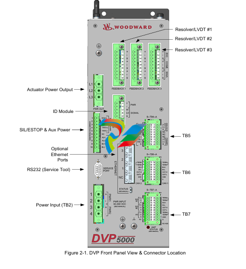
All terminals and connectors are located on the front panel of the chassis. Figures 2-2 and 2-3 show the
front panel and outline views. For EMC compliance, mount the DVP with low impedance bond to Earth
ground.
2.6 Fan Assembly Replacement
The fan assembly in the DVP is designed for field replacement if necessary. If one or both fans fail, an
alarm is generated.
The fans are a ball bearing type with a nominal airflow of 51.97 CFM (1.47m3/min) each.
A degraded fan can occasionally be identified by audible noise sounding like a low rumbling or roughness
from the bearings. In this case, it is advisable to replace the fan assembly at the earliest opportunity.
The fan L10 life is rated at 30.000 hours @ 40C. To extend fan life, the DVP switches fan speed at
several internally sensed temperatures to provide optimum balance between cooling and fan life.
Woodward recommends fan assembly replacement every five years of operation.
The fan assembly orderable part number is 8926-1045SPR.
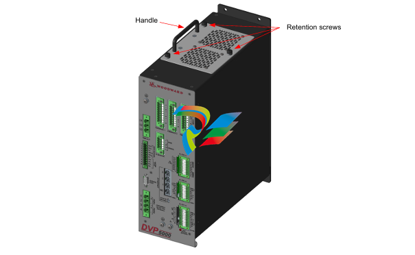
The following procedure is used to replace the fan assembly for the DVP; see Figure 2-5.
Place the actuator into a safe state.
Ensure that input power is removed from the driver.
Unscrew the 3 retention screws. Using the handle, remove the fan assembly from the DVP.
Place the new fan assembly into the connector; tighten the three retention screws.
Apply power to the DVP and ensure the fan alarms are off.
3.1 Power Supply Inputs
The DVP is designed with redundant power supply inputs. These inputs share a common ground and are
isolated from chassis ground. This option allows for redundancy in wiring, connectors, and power sources if
the power sources share a common ground. If one of the inputs is lost, drops low, or experiences temporary
power loss, the other power input will take over without being affected by the first input. The user is provided
four terminals—two plus and two minus. The DVP requires a power supply capable of the specified voltages
and current levels. Please see Table 3-1 for power and fusing information necessary for safe and reliable
operation of the DVP.
3.1.1. Inrush Limiting
The DVP has current inrush limiting built into the design. Power to the CPU occurs rapidly after power
application, but the internal bulk storage capacitors take about eight seconds to fully charge. Inverter
activation is prevented by software until the inrush time has expired. This inrush sequence occurs after
BOTH input power is applied AND EXTERNAL SHUTDOWN input is energized.
3.2 Power Wiring
3.2.1. Recommended Minimum Input Protection:
DVP5000: 15A time delay fuse or 15A breaker
DVP10000 and DVP12000: 30A time delay fuse or 35A breaker (Ambient temperature -40oC to +70oC)
DVP12000: 40A time delay fuse or 45A breaker (Ambient temperature -40oC to +55oC)
High input current transients can be drawn during rapid load movement. The above recommendations
include the transient nature of the electrically driven actuator system. The DVP is not equipped with an
input power switch or breaker. Correct sizing depends on factors such as cable sizing, environment, and
local regulatory requirements. It is recommended that a safety input power switch be provided for
installation and servicing.
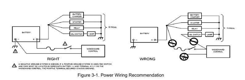
Proper input power wiring to the DVP is crucial to its operation. A circuit breaker meeting the power
supply requirement may be used for this purpose. It is important that proper wiring be applied during
system installation to avoid an unwanted power trip or ground loop. Figure 3-1 illustrates the correct and
incorrect power cable wiring.
3.2.2 Recommendations for Dual and Simplex Power Wiring
The DVP is provided with power terminals suitable for the required voltage and current level. Two positive
and two negative pins are each sized for 8 AWG wire for the DVP5000 and DVP10000. The DVP12000
can accommodate up to 6 AWG wire.
Provision for separate redundant power supplies is provided by dual DC inputs. Each of the inputs is
diode isolated from the main input bus. If one of the supplies is lost, the other input will take over and the
DVP will continue to operate normally. The loss of the input will be annunciated as an alarm.
Woodward recommends that you take advantage of the dual input power wiring configuration; however,
the inputs can be tied together for use with a single power supply.
If a single power source is used to supply power to the DVP, jumpers should be used to apply power to
both sets of input power terminals. The purpose of these jumpers is to ensure that the power supplied
from the source is distributed equally to the two DVP inputs. This minimizes the power dissipated in each
of the DVP input diodes for reduced heat load and improved reliability. When using the jumpers, insert the
positive (+) power input lead from the power source into either the #1 or #3 positions, and the negative (-)
lead into either the #2 or #4 positions as shown in Figure 3-2a.
Some newer versions of the DVP may include power input plugs with jumpers to connect the two positive
and two negative terminals.
In installations where separate dual power sources are connected to the DVP, as shown in Figure 3-2b,
the jumpers are not required.
-
Beckhoff CX2500-B310 | Fieldbus slave module PROFIBUS for CX20xx, CX52x0. CX53x0. CX56x0
-
Beckhoff CX2500-0070 | USB 3.0 module for CX20xx, CX52xx, CX53x0. CX56x0
-
Beckhoff CX2500-0062 | 2.5 Gbit Ethernet module for CX20xx, CX52x0. CX53x0. CX56x0
-
Beckhoff CX2500-1061 | Power over Ethernet module for CX20xx, CX52x0. CX53x0. CX56x0
-
Beckhoff CX2500-1060 | Ethernet module for CX20xx, CX52x0. CX53x0. CX56x0
-
Beckhoff CX2500-0031 | Serial Interface RS485/RS422
-
Beckhoff CX2500-0030 | Serial Interface RS232 for CX20xx, CX52x0. CX53x0. CX56x0
-
Beckhoff CX5230-0195 CPU module
-
Beckhoff CX5230-0190 CPU module
-
Beckhoff CX5230-0175 CPU module,
-
Beckhoff CX5230-0170 CPU module
-
Beckhoff CX5230-0100 CPU module, no operating system, no TwinCAT
-
Beckhoff CU8130-0240 | UPS modul, battery-backed
-
Beckhoff CU8130-0120 | UPS module, battery-backed
-
Beckhoff CU8110-0120 | UPS module, capacitive
-
Beckhoff CU8110-0060 | UPS module, capacitive
-
Beckhoff CX5130-0195 CPU module
-
Beckhoff CX5130-0190 CPU module
-
Beckhoff CX5130-0185 CPU module
-
Beckhoff CX5130-0170 CPU module
-
Beckhoff CX5130-0163 CPU module, Microsoft Windows 10 IoT Enterprise 2019 LTSC, 32 bit
-
Beckhoff CX5130-0162 CPU module
-
Beckhoff CX5130-0161 CPU module
-
Beckhoff CX5130-0160 CPU module
-
Beckhoff CX5130-0155 CPU module
-
Beckhoff CX5130-0150 CPU module
-
Beckhoff CX5130-0143 CPU module
-
Beckhoff CX5130-0142 CPU module
-
Beckhoff CX5130-0140 CPU module
-
Beckhoff CX5130-0135 CPU module
-
Beckhoff CX5130-0130 CPU module
-
Beckhoff CX5130-0125 CPU module
-
Beckhoff CX5130-0123 CPU module
-
Beckhoff CX5130-0122 CPU module
-
Beckhoff CX5130-0121 CPU module
-
Beckhoff CX5130-0115 CPU module,
-
Beckhoff CX5130-0113 CPU module
-
Beckhoff CX5130-0112 CPU module
-
Beckhoff CX5130-0111 CPU module
-
Beckhoff CX5130-0110 CPU module, Microsoft Windows Embedded Compact 7. no TwinCAT
-
Beckhoff CX5130-0100 CPU module, no operating system, no TwinCAT
-
DEIF FAS-113DG Synchronisation & circuit breaker closing
-
DEIF FAS-115DG Synchronisation & circuit breaker closing
-
DEIF HAS-111DG Synchronisation & circuit breaker closing
-
DEIF LSU-122DG Load sharing, paralleling & operation
-
DEIF LSU-114DG Load sharing, paralleling & operation
-
DEIF LSU-113DG Load sharing, paralleling & operation
-
DEIF LSU-112DG Load sharing, paralleling & operation
-
DEIF RMF-112D Frequency relay
-
DEIF RMC-142D Current relay
-
DEIF RMC-132D Current relay
-
DEIF RMC-131D Current relay
-
DEIF RMC-122D Current relay
-
DEIF RMC-121D Current relay
-
DEIF RMC-111D Current relay
-
DEIF MVR-V211 Busbar Protection
-
DEIF MVR-T257 Transformer Differential Protection
-
DEIF MVR-T256 Transformer Differential Protection
-
DEIF MVR-T216 Transformer Differential Protection
-
DEIF MVR-T215 Transformer Protection
-
DEIF MVR-M257 Motor Differential Protection
-
DEIF MVR-M255 Motor Protection
-
DEIF MVR-M215 Motor Protection
-
DEIF MVR-M210 Motor Protection
-
DEIF MVR-G257 Generator Differential Protection
-
DEIF MVR-G215 Generator Protection
-
DEIF MVR-F255 Directional Feeder Protection
-
DEIF MVR-F215 Directional Feeder Protection
-
DEIF MVR-F210 Feeder Protection
-
DEIF MVR-F205 Directional Feeder Protection
-
DEIF MVR-F201 Basic Feeder Protection
-
DEIF MVR-200 series Medium Voltage Relay
-
DEIF MDR-2 Multi-differential relay
-
DEIF LMR-122D Loss of mains relay
-
DEIF LMR-111D Loss of mains relay
-
DEIF APU-4 Advanced G59 and G99 protection unit
-
DEIF iE 650 PLC - The most robust programmable automation controller available
-
DEIF iE 350 PLC - Programmable Automation PLC Controller
-
DEIF iE 250 PLC Versatile and modular intelligent energy PLC controller
-
DEIF PPM-3 EDG Protection and Power Management
-
DEIF AGC 3X 4198000234E AUTOMATIC GENSET CONTROLLER
-
SAUTER ASF123 Damper actuator with spring return
-
SAUTER ASF122 Damper actuator with spring return
-
SAUTER ASF113F122 Damper actuator with spring return
-
SAUTER ASF113F120 Damper actuator with spring return
-
SAUTER ASF112F122 Damper actuator with spring return
-
SAUTER ASF112F120 Damper actuator with spring return
-
SAUTER ASM 124/134 series - ASM134F130 Damper actuator
-
SAUTER ASM 124/134 series - ASM134SF132 Damper actuator
-
SAUTER ASM 124/134 series - ASM124SF132 Damper actuator
-
SAUTER ASM 124/134 series - ASM124F122 Damper actuator
-
SAUTER ASM 124/134 series - ASM124F120 Damper actuator
-
SAUTER Valve actuator ASM 105S/115S series ASM115SF152
-
SAUTER Valve actuator ASM 105S/115S series ASM105SF152
-
SAUTER Valve actuator ASM 105S/115S series ASM115SF132
-
SAUTER Valve actuator ASM 105/115 series ASM105SF132
-
SAUTER Valve actuator ASM 105/115 series ASM115F122
-
SAUTER Valve actuator ASM 105/115 series ASM115F120
-
SAUTER Valve actuator ASM 105/115 series ASM105F122
-
SAUTER Valve actuator ASM 105/115 series ASM105F120
-
SAUTER Valve actuator ASM 105/115 series ASM105F10
-
SAUTER AKF113S Rotating actuator AKF 112/113 series
-
SAUTER AKF113F122 Rotating actuator AKF 112/113 series
-
SAUTER AKF113F120 Rotating actuator AKF 112/113 series
-
SAUTER AKF112F122 Rotating actuator AKF 112/113 series
-
SAUTER AKF112F120 Rotating actuator AKF 112/113 series
-
SAUTER AKM115SAF332: Smart Actuator for ball valve, BACnet/IP
-
SAUTER AKM115SAF232 Rotating Actuator AKM 115SA Smart Actuator
-
SAUTER AKM115SF152 Rotating Actuator AKM 105S/115S Series
-
SAUTER AKM115SF132 Rotating Actuator AKM 105S/115S Series
-
SAUTER AKM105SF132 Rotating Actuator AKM 105S/115S Series
-
SAUTER AKM115F122 Rotating actuator AKM 105/115 series
-
SAUTER Rotating actuator AKM 105/115 series AKM115F120
-
SAUTER Rotating actuator AKM 105/115 series AKM105F122
-
SAUTER Rotating actuator AKM 105/115 series AKM105F120
-
SAUTER Continuous actuator for unit valves, with stroke AXS215S
-
SAUTER Linear valve actuator AXT/AXS series AXT211
-
SAUTER Linear valve actuator AXT/AXS series AXT201
-
SAUTER Linear valve actuator AXM/AXF series AXF217S
-
SAUTER Linear valve actuator AXM/AXF series AXM217S
-
SAUTER AXM217SF404 is an electric actuator for unit valves.
-
SAUTER AXM217SF402 is an electric actuator for unit valves.
-
SAUTER Linear valve actuator AXM/AXF series AXM217
-
SAUTER Linear valve actuator AVF 124/125 series AVF125S
-
SAUTER Linear valve actuator AVF 124/125 series AVF124S
-
SAUTER AVM322S-R Linear valve actuator AVM 234S series
-
SAUTER AVM322-R Linear valve actuator AVM 234S series
-
SAUTER AVM322SF132 Linear valve actuator AVM 234S series

Add: High-tech Software Park, Xiamen City, Fujian Province
Mobile: +86-17750019513(WhatsApp)
Email: yy4291644@gmail.com
Website: https://www.abb-sis.com
.jpg)
.jpg)
.jpg)
.jpg)
.jpg)
.jpg)

-
Beckhoff CX2500-B310 | Fieldbus slave module PROFIBUS for CX20xx, CX52x0. CX53x0. CX56x0
-
Beckhoff CX2500-0070 | USB 3.0 module for CX20xx, CX52xx, CX53x0. CX56x0
-
Beckhoff CX2500-0062 | 2.5 Gbit Ethernet module for CX20xx, CX52x0. CX53x0. CX56x0
-
Beckhoff CX2500-1061 | Power over Ethernet module for CX20xx, CX52x0. CX53x0. CX56x0
-
Beckhoff CX2500-1060 | Ethernet module for CX20xx, CX52x0. CX53x0. CX56x0
