

Fisher™ 4660 High-Low Pressure Pilot
Base/Case: Nitrile
Operating Conditions(1)
Condition
Normal Operating Limits
Ambient
Temperature-59 to 71C (-75 to 160F)
Nominal
Reference
21C (70 F)
Operating Influences on Switch Point Sensitivity
Supply Pressure: ≤0.05% of Bourdon tube rating for a
10% change in supply pressure
Ambient Temperature: ≤2% of Bourdon tube rating
throughout normal operating limits with nominal
reference
Time: ≤1% of Bourdon tube rating over 30 days at
ambient temperature nominal reference
Process Pressure: Range shift or set point drift can
occur if process pressure exceeds the Bourdon tube
rating
Pressure Connections
1/4 NPT internal
Mounting
Panel,
rack,
pipestand, or actuator
Specifications (continued)
Hazardous Area Classification
Complies with the requirements of ATEX Group II
Category 2 Gas and Dust
Ex h IIC Tx Gb
Ex h IIIC Tx Db
Maximum surface temperature (Tx) depends on
operating conditions
Gas: T6
Dust: T71
Meets Customs Union technical regulation TP TC
012/2011 for Groups II/III Category 2 equipment
II Gb c T*X X
III Db c T*X X
Safety Instrumented System Classification
SIL3 capable certified by exida Consulting LLC
Approximate Weight
2.3 kg (5 pounds)
Options
Visual output indication stainless steel panel
mounting flange, set point indication, and
tamper-resistant front cover
Principle of Operation
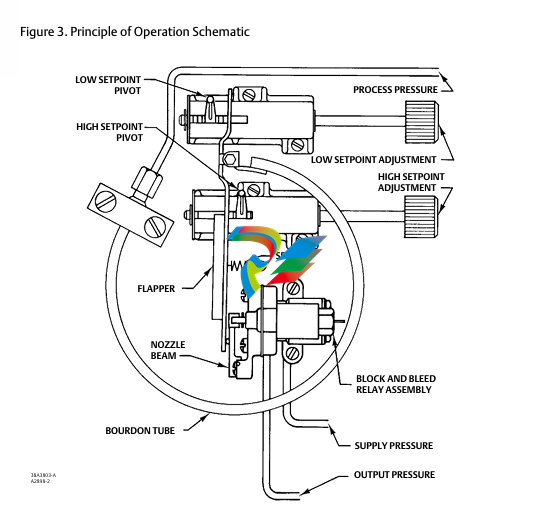
Refer to figure 3.
Process pressure is connected to the Bourdon tube
sensing element. While the process pressure remains
in the adjusted set ranges (between the low set point
and the high set point), the flapper does not contact
either set point pivot. This keeps the nozzle capped
and maintains full output pressure.
As the process pressure decreases below the low set
point value, the radius of arc of the Bourdon tube
contracts. This causes the flapper to contact the low
set point pivot and uncap the nozzle, which blocks
supply pressure and vents (bleeds) output pressure. As
the process pressure increases above the high set
PROCESS PRESSURE
LOW SETPOINT ADJUSTMENT
HIGH SETPOINT
ADJUSTMENT
SPRING
BLOCK AND BLEED
RELAY ASSEMBLY
SUPPLY PRESSURE
OUTPUT PRESSURE
point value, the radius of arc of the Bourdon tube
extends. This causes the flapper to contact the high set
point pivot, also uncapping the nozzle and providing
block-and-bleed action. When the process pressure
returns to the set range, the nozzle is again capped,
switching the relay back to maintain full output
pressure.
Performance
The performance characteristics discussed in the
Performance in Percentage of Bourdon Tube Rating
specification on page 3 and shown in figure 4
illustrate several important functional parameters.
SL represents the low set point and SH represents the
high set point. The set range capability is 3 to 97
percent of the Bourdon tube rating. However, with a
single high-low unit or a high-only/low-only pair, there
is a limit on how close to each other the set points can
be adjusted. This limit is defined as set point ΔPMIN and
is shown as SL′ and SH′.
Trip-to-reset is the combined effect of pilot deadband
and hysteresis. After the pilot has tripped, it
automatically resets when the process pressure
returns to the set range. However, full output pressure
is not instantaneous. The difference between the set
point and reset to full output pressure is the
trip-to-reset zone. This parameter is also a function of
the Bourdon tube rating as shown in figure 4 and
discussed in the Performance in Percentage of
Bourdon Tube Rating specification on page 3.
Repeatability is the switch point deviation around the
set point as a percentage of the Bourdon tube rating.
Applications
Figure 5 shows some of the many ways in which the
4660 high-low pressure pilot may be connected to
accommodate requirements for single and dual
outputs as well as single and dual process pressure
lines. Examples A and D in figure 5 show how a pair of
high-only and low-only pilots are connected to obtain
closer set points as specified by the set point ΔPMIN
values in tables 1 and 2. Example B or C shows
connections for a two-segment flow line configuration
that adheres to API Specification RP14C. Example E
shows a typical connection to an electrical pressure
switch
Installation
Normal installation is with the pilot mounted vertically
and the connections for process pressure, supply
pressure, and output pressure facing down. The supply
medium should be regulated dry air or natural gas with
solid particles removed.
Figures 6 and 7 illustrate the mounting dimensions
and the location of the pressure connections.
Ordering Information
When ordering, specify:
Application
Bourdon tube rating and material
Composition, pressure, and temperature of the
process fluid
Ambient temperature range
Description of application
Construction
Refer to the Specifications table. Review the
information under each specification and in the
referenced tables; specify the desired selection
whenever there is a choice to be made
-
SHINKAWA MODEL VM-5Z5,6,7 POWER SUPPLY UNIT
-
SHINKAWA MODEL VM-5Y1,2,3 RELAY MODULE UNIT
-
SHINKAWA MODEL VM-5P3 PHASE MARKER UNIT
-
SHINKAWA MODEL VM-53 DUAL COMMUNICATION UNIT
-
SHINKAWA MODEL VM-52 BOTTOM HOLD MONITOR
-
SHINKAWA MODEL VM-51 ROD DROP MONITOR
-
SHINKAWA MODEL VM-5R TACHOMETER
-
SHINKAWA MODEL VM-5S DUAL TACHOMETER
-
SHINKAWA MODEL VM-5A DUAL VALVE
-
SHINKAWA MODEL VM-5E DUAL CASE
-
SHINKAWA MODEL VM-5L COMPLEMENTARY INPUT
-
SHINKAWA MODEL VM-5N RAMP DIFFERENTIAL
-
SHINKAWA MODEL VM-5D DUAL DIFFERENTIAL
-
SHINKAWA MODEL VM-5T DUAL THRUST MONITOR
-
SHINKAWA MODEL VM-5C ECCENTRICITY MONITOR
-
SHINKAWA MODEL VM-5C ECCENTRICITY MONITOR
-
SHINKAWA MODEL VM-5M DUAL PATH MONITOR
-
SHINKAWA MODEL VM-5B DUAL ACCELERATION MONITOR
-
SHINKAWA MODEL VM-5B DUAL ACCELERATION MONITOR
-
SHINKAWA MODEL VM-5U DUAL SEISMIC MONITOR
-
SHINKAWA MODEL VM-55 VIBRATION MONITOR
-
SHINKAWA VM-742B1-5 VIBRATION MONITORING SYSTEM CARD
-
Shinkawa PSP-17B P-24-64A P-24-64B Circuit Board Module
-
SHINKAWA MGP-67 PCB
-
Shinkawa JBP-278 P-22-48A-1 P-22-48B-1 Circuit Board Module
-
Shinkawa VM-721B 18-CHANNEL RELAY MODULE
-
Shinkawa FRP-337 P-26-54A P-26-54B Circuit Board Module
-
Shinkawa WKN-142K2-2 Vibration Transmitter
-
SHINKAWA VL-202A08L-1012 Rotor Position Monitor Probe Sensor
-
Shinkawa CPP-128 P-26-74A P-26-74B Circuit Board Module
-
Honeywell 51402755-100 PROCESSOR CARD
-
Honeywell 51107595-100 Power
-
HONEYWELL 51304544-100 Control Board
-
HONEYWELL 51109919-100 BOARD
-
HHoneywell 51204160-175 Digital Input Module
-
Honeywell 51304754-150 High Level Analog Input Module
-
HONEYWELL 51304690-100 DIGITAL INPUT CARD
-
Honeywell 51401635-150 COMM CONTROL
-
HONEYWELL 51204174-175 MC-TAOY 52 ANALOG OUTPUT BOARD
-
HONEYWELL 51400596-100
-
HONEYWELL 51401291-100 board card
-
HONEYWELL 51401642-150 I/O LINK MODULE
-
Honeywell LCN‑E Hub Power Supply 38500148‑300
-
Honeywell LCN‑E Hub redundant 38500143‑202 Twisted‑pair LCN
-
Honeywell LCN‑E Hub non‑redundant,38500143‑102
-
Honeywell Enhanced Micro‑TDC‑3000 System Unit MX‑DTAC01K2
-
Honeywell Enhanced Micro‑TDC‑3000 System Unit MX‑DTAB01K2
-
Honeywell Enhanced Micro‑TDC‑3000 System Unit MT11‑520
-
Honeywell STI‑CE Smart Transmitter Interface 51304516‑150
-
Honeywell STI Smart Transmitter Interface 51304516‑100 MC‑PSTX02
-
Honeywell ulse Counter IOP 51304386‑100 MU‑PPIX02
-
Honeywell DO Digital Output IOP‑CE 51304487‑150 CE version
-
Honeywell DO Digital Output IOP 51304487‑100 MC‑PDOX02
-
Honeywell TDC‑3000 SOE DI IOP,51402625-175 MC‑PDIS12
-
Honeywell TDC‑3000 DI Digital Input IOP‑CE 51304485‑150
-
Honeywell TDC‑3000 DI Digital Input IOP 51304485‑100 MC‑PDIX02
-
Honeywell TDC‑3000 AO Analog Output IOP 51304757‑100 MU‑PAOX02
-
Honeywell TDC‑3000 TC Thermocouple IOP 51304756‑100 MU‑TAMT03
-
Honeywell TDC‑3000 51304755‑100 MU‑TAMR03
-
Honeywell TDC‑3000 LLAI Multiplex AI IOP,51304362‑150
-
Honeywell TDC‑3000 HLAI Analog Input IOP‑CE, 51304363‑150
-
Honeywell TDC‑3000 HLAI Analog Input IOP,51304363‑100.4‑20mA
-
Honeywell TDC‑3000 HPM Power Supply,51401731‑100
-
Honeywell TDC‑3000 Standard 1986.HPM High‑Performance PM CPU,51402362‑100
-
Honeywell TDC‑3000 APM Advanced Process Manager CPU,51304459‑100
-
Honeywell TDC‑3000 Standard 1986.PM Process Manager CPU,51304362‑100
-
Honeywell TDC‑3000 NIM Network Interface Module,51304481‑200
-
Honeywell TDC‑3000 NIM Network Interface Module 51304481‑100
-
Honeywell TDC‑3000 BASIC,LCN Terminator Resistor,30732052‑001.Coaxial
-
Honeywell TDC‑3000 BASIC,Hiway Coupler,30753732‑001
-
Honeywell TDC‑3000 BASIC,LEPIU Low‑Energy PIU,4DP7APCFA309
-
Honeywell TDC‑3000 BASIC,HLPIU High‑Level PIU,4DP7APCFA106
-
Honeywell TDC‑3000 BASIC,Multifunction Controller(TDC‑2000 DHW),4DP7MFA103
-
Honeywell TDC‑3000 BASIC,Extended Controller(TDC‑2000 DHW),4DP7AXA102
-
Honeywell TDC‑3000 BASIC,Basic Controller(TDC‑2000 DHW),4DP7BBA101
-
Honeywell 51305508‑100 TDC‑3000 BASIC,XLCNE2 LCN Extender
-
Honeywell TDC‑3000 BASIC,E‑PLCG PLC Gateway,51400997‑200
-
Honeywell TDC‑3000 BASIC,PLNM Plant Network Module,51401163‑100
-
Honeywell TDC‑3000 BASIC,CG Computer Gateway,80360206‑001
-
Honeywell TDC‑3000 BASIC,HG High‑Speed Gateway,51304526‑100
-
Honeywell TDC‑3000 BASIC,HM History Module,51191596‑200
-
Honeywell TDC‑3000 BASIC,HM History Module,51191596‑100
-
Honeywell TDC‑3000 BASIC,AM Application Module CPU,51401551‑800.K2LCN‑8
-
Honeywell TDC‑3000 BASIC,AM Application Module CPU,51401551‑600.K2LCN‑6
-
Honeywell TDC‑3000 BASIC,AM Application Module CPU,51401551‑400,K2LCN‑4
-
Honeywell TDC‑3000 BASIC,AM Application Module CPU,51401551‑300.K2LCN‑3
-
Honeywell TDC‑3000 BASIC,AM Application Module CPU,51401551‑200,K2LCN‑2
-
Honeywell TDC‑3000 BASIC,US Universal Station CPU,51401288‑200
-
Honeywell TDC‑3000 BASIC,US Universal Station CPU,51401288‑100
-
SHINKAWA VM-21P1 Signal Conditioner 0-50MM 24VDC
-
Shinkawa RiverNew Vibration Transducer VK202 Series
-
Shinkawa Electric VM-3E2 Vibration Monitor Module
-
Shinkawa JBP-47 P-22-48A-1 / P-22-48B-1 Circuit Board Module
-
Shinkawa MODEL VM-5K DUAL VIBRATION MONITOR
-
Shinkawa CMU-15A (CMU15A) Industrial Camera Controller
-
Shinkawa CMU-13A CMU13A Industrial Camera Controller
-
Shinkawa EFU-10 (EFU10) Spark Generator Unit
-
Shinkawa UTC-1000 ZUP-02C Board
-
Shinkawa MDP-89 MDP89 P-24-674A P-24-674B Circuit Board Module
-
Shinkawa CB-1011005001 Signal Cable Assembly
-
SHINKAWA VL-202A08L-1002 Sensor VL-08020L01 Probe Cable F84N1695
-
Shinkawa VK-202A2 Driver & VL-202A08L-1A72 Proximity Sensor Probe
-
SHINKAWA VM-703B VIBRATION MONITORING SYSTEM CARD 2R05-002-P001C
-
Shinkawa BH-150-03 Signal Conditioner / Preamplifier Unit
-
Shinkawa BH-150 Signal Conditioner / Preamplifier Unit
-
Shinkawa Electric VM-3D2 Thrust Monitor Module
-
Shinkawa LCU-37 Monitoring module
-
Shinkawa LCU-44B-06 Local Control Unit Module
-
ABB 3BHE039724R2643 PPD513 high-performance programmable controller module
-
Samsung SSAS21-RTD Resistance Temperature Detector Input Module
-
Samsung SSAS21-AI Analog Input Module
-
Samsung SSAS21-DO Digital Output Module
-
Samsung SSAS21-DI Digital Input Module
-
Samsung SSAS21-CPU Central Processing Unit Module
-
Samsung SMTB-RTD RTD/TC Terminal Board
-
Samsung SMTB-AI Analog Input/Output Terminal Board
-
Samsung SMTB-DO Digital Output Terminal Board
-
Samsung SMTB-DI Digital Input Terminal Board
-
SAMSUNG SMBK-12 IOU Rack Backplane
-
SAMSUNG SMBK-08 IOU Rack Backplane
-
SAMSUNG SMPS-08 Rack Power Module
-
SAMSUNG SMCOM-08 Communication Expansion Card
-
SAMSUNG SMPI-8 Pulse Count Input Module
-
SAMSUNG SMTC-8 Thermocouple Input Module
-
SAMSUNG SMAOC-12 Analog Output Module (12CH)
-
SAMSUNG SMAOC-8 Analog Output Module (8CH)
-
SAMSUNG SMAIC-12 Analog Current Input Module (12CH)
-
SAMSUNG SMRTD-8 RTD Pt100 Temperature Input Module (8CH)

Add: High-tech Software Park, Xiamen City, Fujian Province
Mobile: +86-17750019513(WhatsApp)
Email: yy4291644@gmail.com
Website: https://www.abb-sis.com
.jpg)
.jpg)
.jpg)
.jpg)
.jpg)
.jpg)

-
SHINKAWA MODEL VM-5Z5,6,7 POWER SUPPLY UNIT
-
SHINKAWA MODEL VM-5Y1,2,3 RELAY MODULE UNIT
-
SHINKAWA MODEL VM-5P3 PHASE MARKER UNIT
-
SHINKAWA MODEL VM-53 DUAL COMMUNICATION UNIT
-
SHINKAWA MODEL VM-52 BOTTOM HOLD MONITOR
