

FOXBORO FBM216 HART® Communication Redundant Input Interface Module
cause near end crosstalk at the system end of the
loop wiring cable. Loops using FBM internal power
source do not require Baluns.
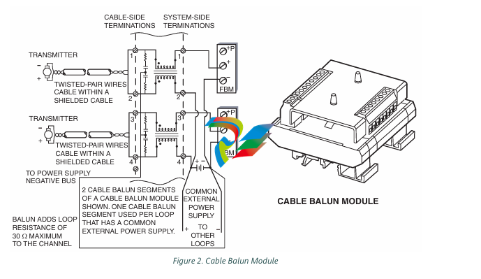
The Cable Balun module contains multiple Baluns.
One Balun segment is interconnected in each loop
powered from an external power supply per the
diagram above. There is one Cable Balun module.
Field Device Channels
VERSION SUPPORTED
HART Protocol v6
INTERFACE
8 group-isolated channels
COMMUNICATION TO THE DEVICE
Point-to-point, master/slave, asynchronous, half
duplex, at 1200 baud
ERROR CHECKING
Parity on each byte, and one CRC check byte
SPEED
2 messages per second
FASTEST ALLOWED ECB BLOCK PERIOD
500 msec
MAXIMUM DISTANCE (FBM216 TO FIELD
DEVICE)
Meets HART FSK physical layer specification
HCF_SPEC-54. Revision 8.1 [up to 3030 m
(10000 ft)](1)
COMPLIANCE VOLTAGE
18 V dc minimum at 20.5 mA
CURRENT INPUTS
Sense Resistor
61.9 Ω nominal
Total Input Resistance
280 Ω minimum
Analog Accuracy (Includes Nonlinearity)
± 0.075%(2) of full scale
Temperature Coefficient
50 PPM/°C
Resolution
15 bits
Update Rate
100 ms
Integration Time
500 ms
Common Mode Rejection
>100 db at 50 or 60 Hz
Normal Mode Rejection
>35 db at 50 or 60 Hz
LOOP POWER SUPPLY PROTECTION
Each channel is galvanically group isolated,
current limited, and voltage regulated.
All inputs are limited by their design to less than
30 mA with a single module installed (60 MA
when redundant modules are installed). If the
current limit circuit shorts out, the current is
limited to about 85 mA.
MAXIMUM LOOP RESISTANCE
280 Ω (not including the field device)(3)
FBM INPUT IMPEDANCE
280 Ω minimum
FBM INTERNAL POWER FOR FIELD DEVICE
24 V dc ±10% common power supply for all
channels. Loop load limited to one device per
channel.
ISOLATION
The channels are not galvanically isolated from
each other, but are galvanically isolated (both
optical and transformer isolation) as a group from
ground and module logic. Inputs use an internal
FBM isolated power supply for field power. The
module withstands, without damage, a potential
of 600 V ac applied for one minute between the
group isolated channels and earth (ground).
CAUTION
This does not imply that these channels are
intended for permanent connection to
voltages of these levels. Exceeding the limits
for input voltages, as stated elsewhere in this
specification, violates electrical safety codes
and may expose users to electric shock
FUNCTIONAL SPECIFICATIONS (CONTINUED)
Fieldbus Communication
Communicates with its associated FCM or FCP via
the redundant 2 Mbps module Fieldbus
Power Requirements
INPUT VOLTAGE RANGE (REDUNDANT)
24 V dc ±5%
CONSUMPTION
7 W (maximum)
HEAT DISSIPATION
4 W (maximum)
Regulatory Compliance
ELECTROMAGNETIC COMPATIBILITY (EMC)
European EMC Directive 89/336/EEC
Meets: EN 50081-2 Emission standard
EN 50082-2 Immunity standard
EN 61326 Annex A (Industrial Levels)
CISPR 11. Industrial Scientific and Medical
(ISM) Radio-frequency Equipment -
Electromagnetic Disturbance Characteristics - Limits and Methods of Measurement
Meets Class A Limits
IEC 61000-4-2 ESD Immunity
Contact 4 kV, air 8 kV
IEC 61000-4-3 Radiated Field Immunity
10 V/m at 80 to 1000 MHz
IEC 61000-4-4 Electrical Fast
Transient/Burst Immunity
2 kV on I/O, dc power and communication
lines
IEC 61000-4-5 Surge Immunity
2kV on ac and dc power lines; 1kV on I/O
and communications lines
IEC 61000-4-6 Immunity to Conducted
Disturbances
10 V (rms) at 150 kHz to 80 MHz on I/O,
dc power and communication lines
IEC 61000-4-8 Power Frequency Magnetic
Field Immunity
30 A/m at 50 and 60 Hz
PRODUCT SAFETY
European Low Voltage Directive 73/23/EEC
SAFETY CERTIFICATION (FBM AND CABLE
BALUN)
Underwriters Laboratories (UL) for U.S. and
Canada
UL/UL-C listed as suitable for use in
UL/UL-C listed Class I, Groups A-D;
Division 2; temperature code T4 enclosure
based systems. These modules are also UL
and UL-C listed as associated apparatus for
supplying non-incendive communication
circuits for Class I, Groups A-D hazardous
locations when connected to specified
I/A Series® processor modules as described
in the I/A Series DIN Rail Mounted
Subsystem User’s Guide (B0400FA). Where
power is supplied by the FBM,
communications circuits also meet the
requirements for Class 2 as defined in
Article 725 of the National Electrical Code
(NFPA No.70) and Section 16 of the
Canadian Electrical Code (CSA C22.1).
Conditions for use are as specified in the
I/A Series DIN Rail Mounted Subsystem
User’s Guide (B0400FA).
European Low Voltage Directive 73/23/EEC
and Explosive Atmospheres (ATEX) directive
94/9/EC
CENELEC (DEMKO) certified as EEx nA IIC
T4 for use in CENELEC certified Zone 2
enclosure certified as associated apparatus
for supplying non-incendive field circuits for
Zone 2. Group IIC, potentially explosive
atmospheres when connected to specified
I/A Series processor modules as described
in the I/A Series DIN Rail Mounted
Subsystem User’s Guide (B0400FA). Also,
see Table 1 on page 10.
Calibration Requirements
Calibration of the module or termination assembly is
not required
ENVIRONMENTAL SPECIFICATIONS(4)
Operating
TEMPERATURE
Module-20 to +70°C (-4 to +158°F)
Termination Assembly
PVC-20 to +50°C (-4 to +122°F)
PA-20 to +70°C (-4 to +158°F)
RELATIVE HUMIDITY
5 to 95% (noncondensing)
ALTITUDE-300 to +3.000 m (-1.000 to +10.000 ft)
-
Kollmorgen AKM54G-ANC2DB00 servo motor
-
Kollmorgen S200 Series S20350-VTS SERVO DRIVE
-
KOLLMORGEN AKD-P00606-NBCC-I000 SERVO DRIVE
-
Kollmorgen MV65WKS-CE310/22PB Servo Drive Control Module
-
Kollmorgen S20360-VTS-021 Servo Drive
-
KOLLMORGEN CR06550 High-precision digital servo amplifier
-
KOLLMORGEN DBL5N01050-03S-VV0-S40 Phase AC Synchronous Brushless Servo Motor
-
KOLLMORGEN S70301-NANANA-024 SERVO DRIVE
-
Kollmorgen S20360-VTS S200 Series Servo Drive
-
Kollmorgen RBE-03011-A00 Brushless Frameless Servo Motor
-
KOLLMORGEN AKD-T00306-NBAN-0000 INPUT SERVO DRIVE
-
KOLLMORGEN S700 Servo Controller S70302-NANANA
-
Kollmorgen AKD-P00607-NBEC-0000 400/480VAC 4.40KVA Servo Drive.
-
KOLLMORGEN S70102-NANANA SERVO DRIVE
-
KOLLMORGEN AKM21E-ANSNEH02 PM Servo Motor & PRD-AMPE25EB-00 Servo Drive Array
-
KollMorgen SC1R06260 Servo Drive 1.4/2.2 KVA 115230 Vac
-
Kollmorgen AKD-P00306-NBAN-0000 Servo Drive
-
Kollmorgen TTB2-2042-3052-A DC Motor Industrial Drive 5.5A 185 oz/inIntegrated safety
-
KOLLMORGEN SERVOSTAR 610-AS SERVO AMPLIFIER_SERVOSTAR610AS_S61001
-
KOLLMORGEN Seidel 60WKS-CE240/26PB 26A Servo Drive Module Control 60WKS-M240/26
-
KOLLMORGEN PRD-0016400P-10 & PRD-0016600D-30 Axis Control System Modules
-
KOLLMORGEN Seidel DBL5N01700-03S-000-S40 Servo Motor
-
HIRSCHMANN RS30-0802O6O6SDAP RAIL SWITCH
-
Hirschmann RS20-1600M2T1SDAEHH03.1.02 Rail Switch
-
Hirschmann RSPM20-4T14T1EV9HHS999.9.99 Managed Ethernet Switch
-
Hirschmann BELDEN RS40-0009CCCCSDAPHH09.0.14 / RS400009CCCCSDAPHH09014
-
Hirschmann RS40 Rail Switch RS40-0009CCCCSDAE
-
Hirschmann BELDEN RS30-0802T1T1SDAP / RS300802T1T1SDAP Fully Managed Layer 2 Compact Rail Switch
-
Hirschmann BELDEN RS20-0800M2M2SDAUHH / RS200800M2M2SDAUHH
-
Hirschmann EAGLE30-04022O6TT999SCCY9HSE3F Industrial Firewall Router Switch
-
Hirschmann RS20-1600T1T1SDAEHH09.0.14 RS20 Rail Mount Ethernet Switch
-
Hirschmann EAGLE 0200T1T1TDDY90000HHE05.3.03 Industrial Security Router
-
Hirschmann - BELDEN MIPP-AD-1L9P
-
HIRSCHMANN RSPM20-4Z64Z6TV9HHS9 942 106-999 RAIL SAFETY SWITCH
-
HIRSCHMANN FIBEROPTIC MODULE FIP P/N: OZDFIPG3 T
-
HIRSCHMANN RS20-1600M2M2SDAUHH Ethernet rack-mounted switch
-
BELDEN RS20-0400T1T1SDAEHH04.0.01 / RS200400T1T1SDAEHH04001
-
HIRSCHMANN MM2-4FXM3 MICE Media Module
-
Hirschmann RS20-2400T1T1SDAP / RS20-2400T1T1SDAPHH05.0.02
-
GE MLJ1005B010H00C MLJ Digital Synchromism Check
-
ALSTOM MICROTECH DX21-M2 Digital Excitation Controller
-
HIRSCHMANN BRS20-1200ZZZZ-STCY99HHSES
-
HIRSCHMANN MM3-4FXM2 MICE Media Module
-
Hirschmann RSB20-0800T1T1SAABHH 8Port ENet Rail Switch RSB20
-
Hirschmann MACH102-8TP Ethernet Switch
-
SAACKE DDZ-M marine steam pressure atomizer
-
SAACKE SKV-A marine rotary cup atomizer
-
SAACKE Seavis HMI05e
-
Kollmorgen MMC-SD-2.0-230 Servo Drive 100-240VAC 2KW 10A Output 3PH 100-240VAC
-
Kollmorgen Servo drive CR10550
-
Kollmorgen AKD-P01207-NACN-0054 Servo Driver
-
Kollmorgen S406M-CA-036 Servostar
-
Kollmorgen AKD-B02407-NAAN-0000 Digital Servo Drive
-
Kollmorgen SERVOSTAR S406AM-CA Digital Servo Drive
-
KOLLMORGEN SERVOSTAR 603-AS SERVO AMPLIFIER_SERVOSTAR603AS_S60301
-
Kollmorgen S700 Servo Controller (S70602-NANANA-NA)
-
Kollmorgen MPK411 controller
-
KOLLMORGEN MMC-SD-1.3-460-D Smart Drive
-
KOLLMORGEN AKM21C-CKB2AA-00 / AKM21CCKB2AA00 Servomotor
-
BECKHOFF AX5106-0000-0200 | Digital Compact Servo Drives 1-channel
-
BECKHOFF C3620-0000 INDUSTRIAL COMPUTER (MOTORSHELVES)
-
Beckhoff EK1960-0000 TwinSAFE Compact Controller
-
Beckhoff C6930-0050 Control Cabinet Industrial PC
-
Beckhoff CX1001-0111 Embedded PC CPU Module
-
Beckhoff C6017-0020 | Ultra-compact Industrial PC
-
Beckhoff EK1322 | 2-port EtherCAT P junction with feed-in
-
Beckhoff CP2219-0010 Panel
-
BECKHOFF C6015-0020 ULTRA COMPACT INDUSTRIAL PC
-
BECKHOFF CX2030-0120/Standard CPU Module Embedded PC Windows PLC controller
-
Beckhoff CP7721-1090-0020 Panel PC
-
Beckhoff PC CPU Module CX5130-0175
-
Beckhoff C6920-0050 Control Cabinet
-
Beckhoff EL6631 EtherCAT 2-Port Communication Interface, Profinet RT Controller
-
Beckhoff CP6202-0001-0060 touch screen panel PC
-
Beckhoff CP3916-1002-0000 Multi-Touch Control Panel
-
Beckhoff EP1809-0021 | EtherCAT Box, 16-channel digital input, 24 V DC, 3 ms, M8Preferred type
-
Beckhoff CX8190 PLC Embedded Industrial PC Ethernet Controller
-
Beckhoff CX2100-0914 Power Supply for External
-
Beckhoff Automation CP6906-0001-0000 HMI
-
Beckhoff EP7342-0002 Module
-
Beckhoff CX1020-0112 / CX1100-0910 / CX1020-N010 / CX1100-0003 Windows CPU
-
Beckhoff EP7211-0034 EtherCAT Box 1 Channel Motion Interface
-
Beckhoff C6240-0030 Control cabinet Industrial PC
-
beckhoff motherboard CB1052-0004 CB1052-0004
-
Beckhoff AX2006-AS Servo Drive / Variable Frequency Drive
-
BECKHOFF CP6207-0001-0020 NSMP
-
Beckhoff C6930-1142-0060 Industrial Computer
-
Beckhoff FC7501-0000 interface card
-
Beckhoff CX5140-0175 Embedded PC PLC CPU CX5140 Industrial Controller
-
Beckhoff CP7802-1100-0010 High-End IP65 Control Panel with DVI/USB Extended Interface
-
BECKHOFF CP3716-1058-0010 CONTROL PANEL
-
Beckhoff AX8108-0000 Single-Axis Module
-
Beckhoff CU8851-0000 | USB extension, USB Extended 2.0 receiver box
-
Beckhoff C6017-0030 | Ultra-compact Industrial PC
-
Beckhoff CX1001-0120/CX10010120.cx1000-n001.cx1000-n000 System Overview
-
Beckhoff CPU Module CX5140-0155/4GB CPU Module
-
Beckhoff CP6533-0001-005: Built-in Panel PC with High-Definition Multi-Touch Control
-
Beckhoff EL5042 | EtherCAT Terminal, 2-channel encoder interface, BiSS® C
-
Beckhoff C6920-1080-0040: Premium Control Cabinet Industrial PC
-
Beckhoff C6920-0060 | Control cabinet Industrial PC
-
Beckhoff Embedded-PC CX5010-1121
-
Beckhoff CB3050-0010 Mainboard Motherboard
-
Beckhoff PLC module CX1020-0000
-
Beckhoff Compact Servo Amplifier AX5112-0000-0200
-
Beckhoff CP7812-1056-0010 15" Multitouch Display Control Panel
-
Beckhoff CX5120-0115 /2GB Controller Module
-
Beckhoff CP7201-1000-0000 Industrial Panel PC
-
Beckhoff Servo Motor AM8061-0JH1-0000
-
BECKHOFF CP6503-0001-0050 Built-in Panel PC
-
Beckhoff CP3919-0010 Display G190ETN01.2 19" PCT V04. Multi-touch Control Panel
-
Beckhoff CX5110-0112-9020/000368201 Embedded PC Intel Atom Processor
-
Beckhoff AX8206-0000-0000 | Dual-axis module
-
Beckhoff Nail Operating Terminal CP7032-1031-0010
-
Beckhoff AM8042-0EH1-0000 Servomotor 4.10 Nm (M0), F4 (87 mm)
-
Beckhoff EK9300 | PROFINET RT Bus Coupler
-
Beckhoff CP3224-0020 Multitouch-Panel-PC
-
Beckhoff CP2712-0000 12.1" 24VDC Touch Screen WMD0
-
BECKHOFF CX5240-0195 / 0000289234 Embedded PC 40 GB CFast Card
-
Beckhoff CP6932-1000-0000 Control Panel
-
BECKHOFF CX5120-0121 PLC Module
-
Beckhoff EL3218 | EtherCAT Terminal, 8-channel analog input
-
Beckhoff EL3218 | EtherCAT Terminal, 8-channel analog input
-
Beckhoff C6640-0050 | Control cabinet Industrial PC
-
Beckhoff Cx5130-0120/4GB Embedded-PC
-
BECKHOFF CX2030-0122 PLC PROCESSOR
-
BECKHOFF CX5020-0122 Controller Module
-
Beckhoff CP3915-0000 Multitouch Panel
-
BECKHOFF EL3014 | EtherCAT Terminal
Add: High-tech Software Park, Xiamen City, Fujian Province
Mobile: +86-17750019513(WhatsApp)
Email: yy4291644@gmail.com
Website: https://www.abb-sis.com
.jpg)
.jpg)
.jpg)
.jpg)
.jpg)
.jpg)

-
Kollmorgen AKM54G-ANC2DB00 servo motor
-
Kollmorgen S200 Series S20350-VTS SERVO DRIVE
-
KOLLMORGEN AKD-P00606-NBCC-I000 SERVO DRIVE
-
Kollmorgen MV65WKS-CE310/22PB Servo Drive Control Module
-
Kollmorgen S20360-VTS-021 Servo Drive
