

Foxboro E69F Current-to-Pneumatic Signal Converter
Figure 8.
4. Loosen 5/16-inch bellows locknut. Note reference line on bellows. Rotate bellows1 so that reference line moves toward motor to decrease span or away from motor to increase span until the error is within ±2%. Tighten bellows locknut.
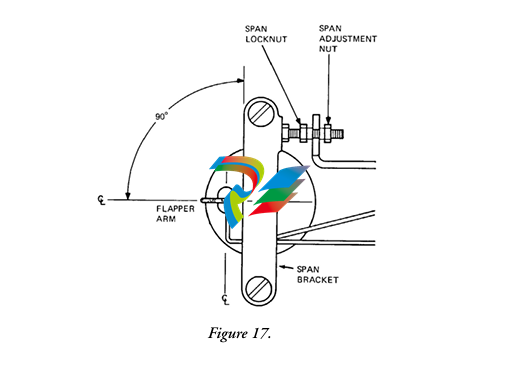
Repeat Steps 2 and 3. 5. SeeFigure 99. Loosen the 5/16-inch span locknut and turn the 5/16-inch span adjustment nut a proportional amount (noted in Step 3) based on the following: 1/6 of a turn (point to point on the hexagonal nut) corrects the error by 0.5%.
1. Bellows Assembly is on an eccentric.
7
MI 018-430 – June 2005
CAUTION
The span locknut must be loosened prior to span adjustment. Do not force nuts against each other to make small span changes. Forcing nuts together could result in
stripping of threads.
6. Disregard output changes that occur when span adjustment is made. Tighten span locknut.
CAUTION
Do not overtighten span locknut when locking in place as threads could become
stripped.
Figure 9.
Figure 10.
7. Apply 12 mA (50%) input to converter and adjust output (zero screw) to 60 kPa or 9 psi (50%).

8. Apply 20 mA (100%) input and check output for 100 kPa or 15 psi (100%). If output is not correct, repeat Steps 5 through 7.
9. Apply 4 mA (0%) and check output for 20 kPa or 3 psi (0%). If necessary, readjust zero screw for correct output.
10. Apply 100% input and check output. If output is not correct, repeat Steps 5 and 8 until both 0% and 100% outputs are correct.
Maintenance
Relay Maintenance
To Remove Relay
Remove the two large screws and pry off relay. SeeFigure 1111. A gasket is supplied with each replacement relay. For maintenance details, see Instruction MI 011-493 (Model 40G) or MI 011-491 (Model 40D).
CAUTION
If converter is equipped with explosionproof cover, three flame arresters are present.
Arresters must remain in place for explosionproof protection.
Figure 11.
To Clean Restrictor
Remove relay. See“To Remove Relay” procedure.
Clean by inserting a 0.1 mm (0.005 in) diameter wire (or Foxboro cleaning wire, Part 0042527) through orifice.
9
MI 018-430 – June 2005
Converter Modifications
NOTE
Foxboro does not consider the following modifications a field conversion. They are considered factory modifications due to the complexity of the procedures and the large amount of time required to perform them. If the modifications must be made in the field, use the following procedures and contact Foxboro for additional
assistance.
To Reverse Converter Action
The existing action of the converter is indicated by the marking on the exposed top of the motor cover: INC-INC (increasing input produces an in
creasing output), or INC-DEC (increasing
input produces a de
creasing output). When reinstalling the motor (Step 9 below), the exposed marking on the motor cover must indicate the desired action. 1. Disconnect instrument from installation (input wiring, air lines, and mounting bolts). 2. Remove two screws holding span bracket. SeeFigure 1212.
Figure 12.
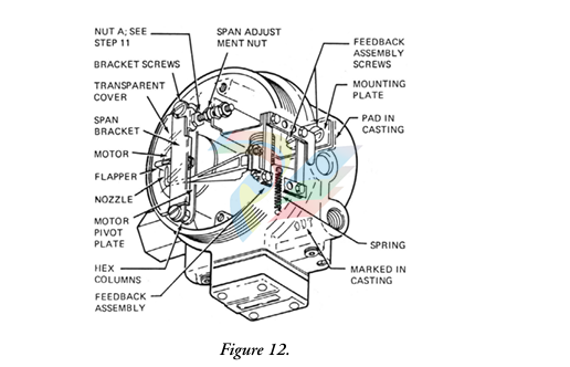
3. Remove two screws holding feedback assembly (with bellows). Note routing of tubing for later replacement.
NOTE
Do not remove mounting plate from feedback assembly. Remove as a unit.
4. Lift aside feedback assembly (do not damage nozzle) to expose spring on bottom of case. Slide transparent cover off span bracket as shown inFigure 1313. Unhook spring from motor bracket.
(For convenience, feedback assembly can be removed entirely by disconnecting tubing. Note identification of tubing for later reconnection.)
10
MI 018-430– June 2005
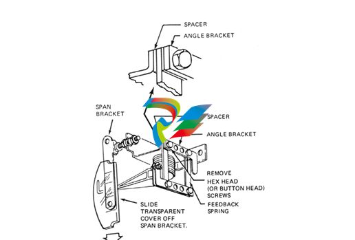
5. On feedback assembly, remove two hex head (formerly buttonhead) screws. Interchange locations of angle bracket and spacer. SeeFigure 1313.
Reinstall hex head screws and tighten to a torque of 3.4 to 4.0 N•m (30 to 35 lb•in). Switching locations of angle bracket and spacer allows the Ni-Span angle bracket to correct for temperature induced errors in the INC-DEC mode.
Figure 13shows parts in INC-INC arrangement.
Figure 13.
6. Remove hex columns (use 5/16-inch wrench), and lift off motor pivot plate. SeeFigure 1212.
7. Lift out motor. Carefully lift flapper straight up from flapper arm on motor. Do not deform flapper. Holding on to flapper arm on other end of motor while removing will prevent internal motor flexure deformation.
8. Remove two screws holding bracket to bottom of motor. SeeFigure 1414. Invert motor and reinstall bracket (on side of motor that was formerly on top).
11
MI 018-430 – June 2005
Figure 14.
9. Wind excess wire clockwise around motor and carefully place motor into position in the case assuring that bottom arm is
-
Beckhoff CX5620-0225 CPU module
-
Beckhoff CX5620-0220 CPU module
-
Beckhoff CX5620-0215 CPU module, Beckhoff RT Linux®
-
Beckhoff CX5620-0210 CPU module, Beckhoff RT Linux®
-
Beckhoff CX5620-0195 CPU module
-
Beckhoff CX5620-0190 CPU module
-
Beckhoff CX5620-0185 CPU module
-
Beckhoff CX5620-0175 CPU module
-
Beckhoff CX5620-0170 CPU module
-
Beckhoff CX5620-0163 CPU module
-
Beckhoff CX5620-0162 CPU module
-
Beckhoff CX5620-0161 CPU module
-
Beckhoff CX5620-0160 CPU module
-
Beckhoff CX5620-0100 CPU module
-
Beckhoff CX5120-0195 CPU module
-
Beckhoff CX5120-0190 CPU module
-
Beckhoff CX5120-0185 CPU module
-
Beckhoff CX5120-0175 CPU module
-
Beckhoff CX5120-0170 CPU module
-
Beckhoff CX5120-0163 CPU module
-
Beckhoff CX5120-0162 CPU module,
-
Beckhoff CX5120-0161 CPU module
-
Beckhoff CX5120-0160 CPU module,
-
Beckhoff CX5120-0150 CPU module
-
Beckhoff CX5120-0143 CPU module
-
Beckhoff CX5120-0142 CPU module
-
Beckhoff CX5120-0141 CPU module, Microsoft Windows 10 IoT Enterprise 2016 LTSB
-
Beckhoff CX5120-0140 CPU module
-
Beckhoff CX5120-0130 CPU module
-
Beckhoff CX5120-0123 CPU module
-
Beckhoff CX5120-0122 CPU module
-
Beckhoff CX5120-0120 CPU module
-
Beckhoff CX5120-0113 CPU module
-
Beckhoff CX5120-0112 CPU module
-
Beckhoff CX5120-0111 CPU module
-
Beckhoff CX5120-0110 CPU module
-
Beckhoff CX5120-0100 CPU module, no operating system
-
Beckhoff C6017-0040 | Fanless ultra-compact Industrial PC
-
Beckhoff C6017 | Fanless ultra-compact Industrial PC
-
Beckhoff C6015-0030 | Fanless ultra-compact Industrial PC
-
Beckhoff C6015-0040 | Fanless ultra-compact Industrial PC
-
Beckhoff C6015 | Fanless ultra-compact Industrial PC
-
Beckhoff CX2500-M510 | Fieldbus master module
-
Beckhoff CX2500-M310 | Fieldbus master module
-
Beckhoff CX2500-B510 | Fieldbus slave module
-
Beckhoff CX2500-B310 | Fieldbus slave module PROFIBUS for CX20xx, CX52x0. CX53x0. CX56x0
-
Beckhoff CX2500-0070 | USB 3.0 module for CX20xx, CX52xx, CX53x0. CX56x0
-
Beckhoff CX2500-0062 | 2.5 Gbit Ethernet module for CX20xx, CX52x0. CX53x0. CX56x0
-
Beckhoff CX2500-1061 | Power over Ethernet module for CX20xx, CX52x0. CX53x0. CX56x0
-
Beckhoff CX2500-1060 | Ethernet module for CX20xx, CX52x0. CX53x0. CX56x0
-
Beckhoff CX2500-0031 | Serial Interface RS485/RS422
-
Beckhoff CX2500-0030 | Serial Interface RS232 for CX20xx, CX52x0. CX53x0. CX56x0
-
Beckhoff CX5230-0195 CPU module
-
Beckhoff CX5230-0190 CPU module
-
Beckhoff CX5230-0175 CPU module,
-
Beckhoff CX5230-0170 CPU module
-
Beckhoff CX5230-0100 CPU module, no operating system, no TwinCAT
-
Beckhoff CU8130-0240 | UPS modul, battery-backed
-
Beckhoff CU8130-0120 | UPS module, battery-backed
-
Beckhoff CU8110-0120 | UPS module, capacitive
-
Beckhoff CU8110-0060 | UPS module, capacitive
-
Beckhoff CX5130-0195 CPU module
-
Beckhoff CX5130-0190 CPU module
-
Beckhoff CX5130-0185 CPU module
-
Beckhoff CX5130-0170 CPU module
-
Beckhoff CX5130-0163 CPU module, Microsoft Windows 10 IoT Enterprise 2019 LTSC, 32 bit
-
Beckhoff CX5130-0162 CPU module
-
Beckhoff CX5130-0161 CPU module
-
Beckhoff CX5130-0160 CPU module
-
Beckhoff CX5130-0155 CPU module
-
Beckhoff CX5130-0150 CPU module
-
Beckhoff CX5130-0143 CPU module
-
Beckhoff CX5130-0142 CPU module
-
Beckhoff CX5130-0140 CPU module
-
Beckhoff CX5130-0135 CPU module
-
Beckhoff CX5130-0130 CPU module
-
Beckhoff CX5130-0125 CPU module
-
Beckhoff CX5130-0123 CPU module
-
Beckhoff CX5130-0122 CPU module
-
Beckhoff CX5130-0121 CPU module
-
Beckhoff CX5130-0115 CPU module,
-
Beckhoff CX5130-0113 CPU module
-
Beckhoff CX5130-0112 CPU module
-
Beckhoff CX5130-0111 CPU module
-
Beckhoff CX5130-0110 CPU module, Microsoft Windows Embedded Compact 7. no TwinCAT
-
Beckhoff CX5130-0100 CPU module, no operating system, no TwinCAT
-
DEIF FAS-113DG Synchronisation & circuit breaker closing
-
DEIF FAS-115DG Synchronisation & circuit breaker closing
-
DEIF HAS-111DG Synchronisation & circuit breaker closing
-
DEIF LSU-122DG Load sharing, paralleling & operation
-
DEIF LSU-114DG Load sharing, paralleling & operation
-
DEIF LSU-113DG Load sharing, paralleling & operation
-
DEIF LSU-112DG Load sharing, paralleling & operation
-
DEIF RMF-112D Frequency relay
-
DEIF RMC-142D Current relay
-
DEIF RMC-132D Current relay
-
DEIF RMC-131D Current relay
-
DEIF RMC-122D Current relay
-
DEIF RMC-121D Current relay
-
DEIF RMC-111D Current relay
-
DEIF MVR-V211 Busbar Protection
-
DEIF MVR-T257 Transformer Differential Protection
-
DEIF MVR-T256 Transformer Differential Protection
-
DEIF MVR-T216 Transformer Differential Protection
-
DEIF MVR-T215 Transformer Protection
-
DEIF MVR-M257 Motor Differential Protection
-
DEIF MVR-M255 Motor Protection
-
DEIF MVR-M215 Motor Protection
-
DEIF MVR-M210 Motor Protection
-
DEIF MVR-G257 Generator Differential Protection
-
DEIF MVR-G215 Generator Protection
-
DEIF MVR-F255 Directional Feeder Protection
-
DEIF MVR-F215 Directional Feeder Protection
-
DEIF MVR-F210 Feeder Protection
-
DEIF MVR-F205 Directional Feeder Protection
-
DEIF MVR-F201 Basic Feeder Protection
-
DEIF MVR-200 series Medium Voltage Relay
-
DEIF MDR-2 Multi-differential relay
-
DEIF LMR-122D Loss of mains relay
-
DEIF LMR-111D Loss of mains relay
-
DEIF APU-4 Advanced G59 and G99 protection unit
-
DEIF iE 650 PLC - The most robust programmable automation controller available
-
DEIF iE 350 PLC - Programmable Automation PLC Controller
-
DEIF iE 250 PLC Versatile and modular intelligent energy PLC controller
-
DEIF PPM-3 EDG Protection and Power Management
-
DEIF AGC 3X 4198000234E AUTOMATIC GENSET CONTROLLER
-
SAUTER ASF123 Damper actuator with spring return
-
SAUTER ASF122 Damper actuator with spring return

Add: High-tech Software Park, Xiamen City, Fujian Province
Mobile: +86-17750019513(WhatsApp)
Email: yy4291644@gmail.com
Website: https://www.abb-sis.com



-
Beckhoff CX5620-0225 CPU module
-
Beckhoff CX5620-0220 CPU module
-
Beckhoff CX5620-0215 CPU module, Beckhoff RT Linux®
-
Beckhoff CX5620-0210 CPU module, Beckhoff RT Linux®
-
Beckhoff CX5620-0195 CPU module
