

Foxboro E69F Current-to-Pneumatic Signal Converter
E69F Current-to-Pneumatic
Signal Converter
Introduction
General Description
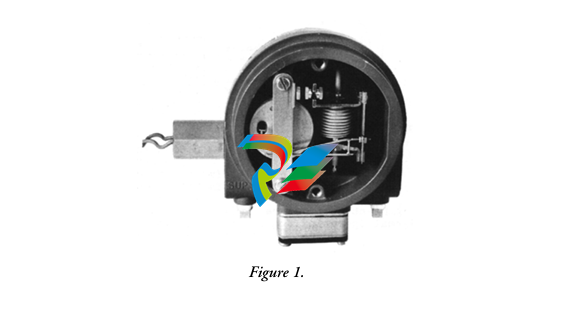
TheE69F Current-to-Pneumatic Signal Converter (Figure 1) is a field-mounted instrument that
transforms a dc milliampere input signal to a proportional pneumatic output signal.
This output signal can be used either to operate such pneumatic devices as dampers, and valve
actuators, and so forth, or as the input to various pneumatic instruments.
Principle of Operation
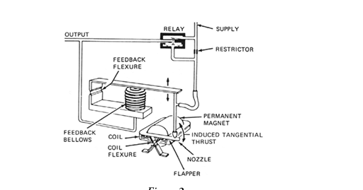
A dc milliampere input signal is converted to a proportional pneumatic output signal in the fol
lowing manner (see Figure 2). A coil positioned in the field of a permanent magnet reacts to the
current by producing a tangential thrust proportional to the input signal flowing through it. The
thrust, acting through coil flexures, varies the gap between a flapper and a nozzle. This causes a
change in the output pressure of the relay, which is also the converter output pressure. This pres
sure is fed to a feedback bellows which exerts a force on a feedback flexure to move the nozzle and
establish a throttling relationship between the flapper and the nozzle
Standard Specifications
Input and Output Ranges
Input Ranges (mA)
kPa
Output Ranges(3)
4 to 20(1)
or
20 to 100
40 to 200
7 to 125
7 to 220
psi
3 to 15
3 to 27
6 to 30
1 to 18
1 to 32
10 to 50(2)
(1) 4 to 12 or 12 to 20 mA. Split ranges available with addition of a flat spring.
(2) 10 to 30 or 30 to 50 mA. Split ranges available with addition of a flat spring.
(3) Direct or reverse, as specified.
NOTE
Ranges are listed in kPa and psi. For alternative ranges in kg/cm2 or bar, divide
applicable kPa values by 100.
Supply Pressure
Nominal
140 kPa or 20 psi
Limits
130 and 160 kPa or 19 and 23 psi
240 kPa or 35 psi
225 and 260 kPa or 33 and 38 psi
Supply pressure must not be less than 20 kPa or 3 psi above the maximum signal.
Input Resistance
4 to 20 mA Input: 170 Ω
10 to 50 mA Input: 27 Ω
Air Consumption
20 to 100 kPa or 3 to 15 psi output:
40G Relay: 0.5 m3/h (0.30 cfm) at standard conditions.
All other outputs: 40D Relay:
1.3 m3/h (0.75 cfm) at standard conditions with 140 kPa or 20 psi supply.
1.7 m3/h (1.0 cfm) at standard conditions with 240 kPa or 35 psi supply.
Ambient Temperature Limits
Normal Operating Conditions:-30 and +60°C (-20 and +140°F)
Operative Limits: -40 and +80°C (-40 and +180°F)
Calibrated Accuracy
±0.5% of span; but ±2% of span with output signals of 7 to 125 and 7 to 220 kPa or 1 to 18
and 1 to 32 psi
Mass
(Approximate) 2.3 kg (5 lb)
Product Safety
For electrical classification of converter, refer to data plate. For conditions of certification, refer to
Calibration
For simplicity, the procedure below assumes a converter with a 4 to 20 mA input and a 20 to
100 kPa or 3 to 15 psi output. For other ranges, substitute the applicable values. The specific
input and output are listed on the converter data plate.
Equipment Setup
Calibration setup is shown in Figure 7.
Any adjustment to the span will interact with the zero adjustment and will change
the initial zero setting. Therefore, any adjustment made to the span must be
followed by readjustment of zero.
1. Set up equipment as shown in Figure 7.
2. Apply 12 mA (50%) input to converter and adjust output (zero screw) to 60 kPa or
9 psi (50%). See Figure 8.
3. Apply 20 mA (100%) input to converter and note amount of error above or below
100 kPa or 15 psi (100%) output. If error is greater than ±2% (1.6 kPa or 0.025 psi),
perform Step 4. If error is less than ±2%, proceed to Step 5.
4. Loosen 5/16-inch bellows locknut. Note reference line on bellows. Rotate bellows1 so
that reference line moves toward motor to decrease span or away from motor to
increase span until the error is within ±2%. Tighten bellows locknut.
Repeat Steps 2 and 3.
5. See Figure 9. Loosen the 5/16-inch span locknut and turn the 5/16-inch span
adjustment nut a proportional amount (noted in Step 3) based on the following: 1/6
of a turn (point to point on the hexagonal nut) corrects the error by 0.5%.
7. Apply 12 mA (50%) input to converter and adjust output (zero screw) to 60 kPa or
9 psi (50%).
8
8. Apply 20 mA (100%) input and check output for 100 kPa or 15 psi (100%). If
output is not correct, repeat Steps 5 through 7.
9. Apply 4 mA (0%) and check output for 20 kPa or 3 psi (0%). If necessary, readjust
zero screw for correct output.
10. Apply 100% input and check output. If output is not correct, repeat Steps 5 and 8
until both 0% and 100% outputs are correct.
Maintenance
Relay Maintenance
To Remove Relay
Remove the two large screws and pry off relay. See Figure 11. A gasket is supplied with each
replacement relay.
For maintenance details, see Instruction MI 011-493 (Model 40G) or MI 011-491 (Model 40D).
To Clean Restrictor
Remove relay. See “To Remove Relay” procedure.
Clean by inserting a 0.1 mm (0.005 in) diameter wire (or Foxboro cleaning wire, Part 0042527)
through
t up equipment as shown inFigure 77. 2. Apply 12 mA (50%) input to converter and adjust output (zero screw) to 60 kPa or 9 psi (50%). SeeFigure 88.
3. Apply 20 mA (100%) input to converter and note amount of error above or below 100 kPa or 15 psi (100%) output. If error is greater than ±2% (1.6 kPa or 0.025 psi), perform Step 4. If error is less than ±2%, proceed to Step 5.
-
SAMSUNG SSAS-PRO SPTB-AI dedicated analog input terminal board
-
SAMSUNG SSAS-PRO SPTB-DO dedicated digital output terminal board
-
SAMSUNG SSAS-PRO SPTB-DI dedicated terminal board
-
SAMSUNG SSAS-PRO SPBK-X32-12 Heavy-duty 8-slot system chassis backplane
-
SAMSUNG SSAS-PRO SPBK-X32-08 Heavy-duty 8-slot system chassis backplane
-
SAMSUNG SSAS-PRO SPSU-X32 heavy-duty rack-mounted
-
SAMSUNG SSAS-PRO SPIRU-16 versatile universal mixed I/O module
-
SAMSUNG SSAS-PRO SPRI-16 RTD Temperature Input Module
-
SAMSUNG SSAS-PRO SPAO-8 Analog Output Module
-
SAMSUNG SSAS-PRO SPAI-16 Analog Input Module
-
SAMSUNG SSAS-PRO SPRDO-16 Relay digital output module
-
SAMSUNG SSAS-PRO SPDO-16 (Transistor Digital Output Module)
-
SAMSUNG SSAS-PRO SPDI-24 high-density digital input module
-
SAMSUNG SPDI-16 (Digital Input Module)
-
ADLINK 3U Enclosures & Systems AD-3100
-
Power Supplies cPS-H300S/AC ADLINK
-
CPCI Serial Peripheral cPCI-A3H10 ADLINK
-
ADLINK CPCI Serial Peripheral cPCI-A3XMC
-
CPCI Serial Peripheral cPCI-A3H20 ADLINK
-
CPCI Serial Peripheral cPCI-A3MXM ADLINK
-
ADLINK CPCI Serial Peripheral cPCI-A3COM
-
ADLINK CPCI Serial Peripheral cPCI-A3USB
-
ADLINK CPCI Serial Peripheral cPCI-A3ETH
-
CPCI Serial Peripheral cPCI-A3CAN ADLINK
-
3U CompactPCI Serial Blades cPCI-A3525 Series
-
3U CompactPCI Serial Blades cPCI-A3535 Series ADLINK
-
CompactPCI Backplanes cBP-6402 ADLINK
-
ADLINK CompactPCI Backplanes cBP-6402R
-
ADLINK CompactPCI Backplanes cBP-6105R
-
CompactPCI Backplanes cBP-6405R ADLINK
-
CompactPCI Backplanes cBP-6108F ADLINK
-
CompactPCI Backplanes cBP-6108R ADLINK
-
CompactPCI Backplanes cBP-6014R ADLINK
-
ADLINK 6U Enclosures & Systems cPCIS-6130R
-
ADLINK 6U Enclosures & Systems cPCIS-6230R/ 6240R Series
-
ADLINK 6U Enclosures & Systems cPCIS-6235R
-
ADLINK 6U Enclosures & Systems cPCIS-6400X Series
-
ADLINK 6U Enclosures & Systems cPCIS-6400U Series
-
ADLINK 6U Enclosures & Systems cPCIS-6418U
-
ADLINK 6U Enclosures & Systems cPCIS-3300BLS
-
ADLINK 6U Enclosures & Systems cPCIS-3320/AC
-
ADLINK Power Supplies cPS-H640/AC
-
ADLINK Power Supplies cPS-H640/48
-
ADLINK 6U Rear Transition Modules cPCI-R6100 Series
-
ADLINK 6U Rear Transition Modules cPCI-R6002 Series
-
ADLINK 6U Rear Transition Modules cPCI-R6600 Series
-
ADLINK 6U CompactPCI 2.0 Blades cPCI-6660
-
ADLINK 6U CompactPCI 2.0 Blades cPCI-6636(KL) Series
-
ADLINK 6U CompactPCI 2.0 Blades cPCI-6640 Series
-
ADLINK 6U CompactPCI 2.0 Blades cPCI-6540 Series
-
ADLINK CompactPCI Backplanes cBP-3064
-
ADLINK CompactPCI Backplanes cBP-3213PR
-
ADLINK 3U Enclosures & Systems cPCIS-2500 Series
-
ADLINK 3U Enclosures & Systems cPCIS-2630 Series
-
ADLINK 3U Enclosures & Systems cPCIS-2632 Series
-
ADLINK 3U Enclosures & Systems cPCIS-2642 Series
-
ADLINK U Enclosures & Systems cPCIS-2633 Series
-
ADLINK U Enclosures & Systems cPCIS-ET1100 Series
-
ADLINK Power Supplies cPS-H325/AC
-
ADLINK Power Supplies cPS-H325/48
-
ADLINK Power Supplies cPS-H325/110
-
ADLINK Power Supplies cPS-H325/24
-
ADLINK PCI-7841/cPCI-7841 Dual-port Isolated CAN Interface Cards
-
ADLINK Peripherals & Accessories cPCI-3548
-
ADLINK Peripherals & Accessories cPCI-8301
-
ADLINK Peripherals & Accessories cPCI-3W10
-
ADLINK Analog Output cPCI-6208/6216 Series
-
ADLINK Multi-Function DAQ cPCI-9116
-
ADLINK 3U CompactPCI Blades CT-3620
-
ADLINK 3U CompactPCI Blades cPCI-3620
-
ADLINK 3U CompactPCI Blades cPCI-3620
-
ADLINK 3U CompactPCI Blades cPCI-3630
-
ADLINK 3U CompactPCI Blades cPCI-3640 Series
-
3U CompactPCI Blades cPCI-3520 Series
-
ADLINK IMB-M42H ATX Motherboards
-
Adlink PCIe-GIE74 /PCIe-GIE74V Frame Grabbers / Video Capture Cards
-
ADLINK USB-1605 Removable screw terminal blocks or high-density D-Sub
-
Adlink ETX-NR667-L7400/LXE ETX Module
-
ADLINK NuPRO-842LV/P industrial control motherboard
-
ADLINK cPCI-8994 Serial Communication
-
ADLINK / PCI-7432 Digital I/O
-
ADLINK IEC-915GV Compact industrial-grade fanless embedded system
-
ADLINK ADLINK, PLX / PCI-7296 Digital I/O
-
ADLINK HPCI-14S12U 0040 Backplane Selection Guide
-
ADLINK MXE-5500 /MXE-5501/M16G (G) Fanless Embedded Computer
-
Adlink Multi-Function DAQ PCI-9112
-
ADLINK NuPRO-852LV Control Board
-
ADLINK CompactPCI cPCI-7432R Digital I/O Module
-
ADLINK NUPRO-E320LV PICMG Single Board Computers
-
ADLINK PICMG Single Board Computers NuPRO-E72
-
ADLINK PICMG Single Board Computers NuPRO-865
-
Vibro-Meter Rack VM600SYSMK2-ABE04x 6U 19-inch rack Mk2 system
-
Vibro-Meter Relay expansion RLC16 Mk2 SIL2 (single card) 600-044L
-
Vibro-Meter Relay expansion RLC16 Mk2 SIL2 600-04
-
Vibro-Meter Relay expansion RLC16 Mk2 600-045L
-
Vibro-Meter Relay expansion RLC16 Mk2 600-045
-
Vibro-Meter I/O interface card IOCN Mk2 600-051
-
Vibro-Meter CPU controller CPUM Mk2 600-050
-
Vibro-Meter I/O interface card IOC10 Mk2 (rear card) 600-046
-
Vibro-Meter Temperature / Analog Acquisition AMC10 Mk2 600-042
-
Vibro-Meter I/O interface card IOC4 Mk2 600-043
-
Vibro-Meter Protective measuring card MPC4 Mk2 SIL2 601-041-A10
-
Vibro-Meter Protective measuring card MPC4 Mk2 601-041-A0
-
Vibro-Meter PSU-VM600 VM600 Rack Power Module
-
Vibro-Meter ABE056 - 1U ultra-thin single-rack
-
Vibro-Meter ABE046 - 6U 19-inch rack
-
Vibro-Meter ABE045 - 6U 19-inch rack
-
Vibro-Meter ABE044 - 6U 19-inch rack (with expansion slots)
-
Vibro-Meter ABE042 6U 19-inch rack (4 slots)
-
Vibro-Meter I/O interface card XIO16T
-
Vibro-Meter XMC16 16-channel combustion monitoring card
-
Vibro-Meter XMV16 - 16-channel vibration condition monitoring card
-
Vibro-Meter RLC16 Relay Card
-
Vibro-Meter IRC4 Intelligent Relay Card
-
Vibro-Meter IOCR2 input/output rear interface card
-
Vibro-Meter CPUR2 Central Processing and Controller Card
-
Vibro-Meter I/O interface card - IOCR
-
VIBRO-METER CPU controller CPUR
-
VIBRO-METER IOCN 200-585-000-322 I/O interface card
-
VIBRO-METER IOCN 200-585-000-321 I/O Interface Card
-
VIBRO-METER 200-595-074-323 VM600 system CPU management card, non-redundant
-
VIBRO-METER CPUM 200-595-074-322 CPU Controller
-
VIBRO-METER CPU controller CPUM 200-595-070-321
-
Vibro-Meter IOC8T VM600 Mk1 I/O Interface Card
-
Vibro-Meter AMC8 Analog Monitoring Card
-
VIBRO-METER IOC4G2 I/O interface card
-
VIBRO-METER MPC4G2 Protective measuring card
-
VIBRO-METER IOC4T 200-560-101-017 VM600 Mk1 Isolated I/O Interface Card, equipped with MPC4

Add: High-tech Software Park, Xiamen City, Fujian Province
Mobile: +86-17750019513(WhatsApp)
Email: yy4291644@gmail.com
Website: https://www.abb-sis.com
.jpg)
.jpg)
.jpg)
.jpg)
.jpg)
.jpg)

-
SAMSUNG SSAS-PRO SPTB-AI dedicated analog input terminal board
-
SAMSUNG SSAS-PRO SPTB-DO dedicated digital output terminal board
-
SAMSUNG SSAS-PRO SPTB-DI dedicated terminal board
-
SAMSUNG SSAS-PRO SPBK-X32-12 Heavy-duty 8-slot system chassis backplane
-
SAMSUNG SSAS-PRO SPBK-X32-08 Heavy-duty 8-slot system chassis backplane
