

Foxboro E69F Current-to-Pneumatic Signal Converter
E69F Current-to-Pneumatic
Signal Converter
Introduction
General Description
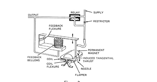
TheE69F Current-to-Pneumatic Signal Converter (Figure 1) is a field-mounted instrument that
transforms a dc milliampere input signal to a proportional pneumatic output signal.
This output signal can be used either to operate such pneumatic devices as dampers, and valve
actuators, and so forth, or as the input to various pneumatic instruments.
Principle of Operation
A dc milliampere input signal is converted to a proportional pneumatic output signal in the fol
lowing manner (see Figure 2). A coil positioned in the field of a permanent magnet reacts to the
current by producing a tangential thrust proportional to the input signal flowing through it. The
thrust, acting through coil flexures, varies the gap between a flapper and a nozzle. This causes a
change in the output pressure of the relay, which is also the converter output pressure. This pres
sure is fed to a feedback bellows which exerts a force on a feedback flexure to move the nozzle and
establish a throttling relationship between the flapper and the nozzle
Standard Specifications
Input and Output Ranges
Input Ranges (mA)

kPa
Output Ranges(3)
4 to 20(1)
or
20 to 100
40 to 200
7 to 125
7 to 220
psi
3 to 15
3 to 27
6 to 30
1 to 18
1 to 32
10 to 50(2)
(1) 4 to 12 or 12 to 20 mA. Split ranges available with addition of a flat spring.
(2) 10 to 30 or 30 to 50 mA. Split ranges available with addition of a flat spring.
(3) Direct or reverse, as specified.
NOTE
Ranges are listed in kPa and psi. For alternative ranges in kg/cm2 or bar, divide
applicable kPa values by 100.
Supply Pressure
Nominal
140 kPa or 20 psi
Limits
130 and 160 kPa or 19 and 23 psi
240 kPa or 35 psi
225 and 260 kPa or 33 and 38 psi
Supply pressure must not be less than 20 kPa or 3 psi above the maximum signal.
Input Resistance
4 to 20 mA Input: 170 Ω
10 to 50 mA Input: 27 Ω
Air Consumption
20 to 100 kPa or 3 to 15 psi output:
40G Relay: 0.5 m3/h (0.30 cfm) at standard conditions.
All other outputs: 40D Relay:
1.3 m3/h (0.75 cfm) at standard conditions with 140 kPa or 20 psi supply.
1.7 m3/h (1.0 cfm) at standard conditions with 240 kPa or 35 psi supply.
Ambient Temperature Limits
Normal Operating Conditions:-30 and +60°C (-20 and +140°F)
Operative Limits: -40 and +80°C (-40 and +180°F)
Calibrated Accuracy
±0.5% of span; but ±2% of span with output signals of 7 to 125 and 7 to 220 kPa or 1 to 18
and 1 to 32 psi
Mass
(Approximate) 2.3 kg (5 lb)
Product Safety
For electrical classification of converter, refer to data plate. For conditions of certification, refer to
Calibration
For simplicity, the procedure below assumes a converter with a 4 to 20 mA input and a 20 to
100 kPa or 3 to 15 psi output. For other ranges, substitute the applicable values. The specific
input and output are listed on the converter data plate.
Equipment Setup
Calibration setup is shown in Figure 7.
Any adjustment to the span will interact with the zero adjustment and will change
the initial zero setting. Therefore, any adjustment made to the span must be
followed by readjustment of zero.
1. Set up equipment as shown in Figure 7.
2. Apply 12 mA (50%) input to converter and adjust output (zero screw) to 60 kPa or
9 psi (50%). See Figure 8.
3. Apply 20 mA (100%) input to converter and note amount of error above or below
100 kPa or 15 psi (100%) output. If error is greater than ±2% (1.6 kPa or 0.025 psi),
perform Step 4. If error is less than ±2%, proceed to Step 5.
4. Loosen 5/16-inch bellows locknut. Note reference line on bellows. Rotate bellows1 so
that reference line moves toward motor to decrease span or away from motor to
increase span until the error is within ±2%. Tighten bellows locknut.
Repeat Steps 2 and 3.
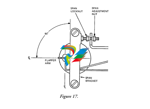
5. See Figure 9. Loosen the 5/16-inch span locknut and turn the 5/16-inch span
adjustment nut a proportional amount (noted in Step 3) based on the following: 1/6
of a turn (point to point on the hexagonal nut) corrects the error by 0.5%.
7. Apply 12 mA (50%) input to converter and adjust output (zero screw) to 60 kPa or
9 psi (50%).
8
8. Apply 20 mA (100%) input and check output for 100 kPa or 15 psi (100%). If
output is not correct, repeat Steps 5 through 7.
9. Apply 4 mA (0%) and check output for 20 kPa or 3 psi (0%). If necessary, readjust
zero screw for correct output.
10. Apply 100% input and check output. If output is not correct, repeat Steps 5 and 8
until both 0% and 100% outputs are correct.
Maintenance
Relay Maintenance
To Remove Relay
Remove the two large screws and pry off relay. See Figure 11. A gasket is supplied with each
replacement relay.
For maintenance details, see Instruction MI 011-493 (Model 40G) or MI 011-491 (Model 40D).
To Clean Restrictor
Remove relay. See “To Remove Relay” procedure.
Clean by inserting a 0.1 mm (0.005 in) diameter wire (or Foxboro cleaning wire, Part 0042527)
through
t up equipment as shown inFigure 77. 2. Apply 12 mA (50%) input to converter and adjust output (zero screw) to 60 kPa or 9 psi (50%). SeeFigure 88.
3. Apply 20 mA (100%) input to converter and note amount of error above or below 100 kPa or 15 psi (100%) output. If error is greater than ±2% (1.6 kPa or 0.025 psi), perform Step 4. If error is less than ±2%, proceed to Step 5.
Figure 8.
4. Loosen 5/16-inch bellows locknut. Note reference line on bellows. Rotate bellows1 so that reference line moves toward motor to decrease span or away from motor to increase span until the error is within ±2%. Tighten bellows locknut.
Repeat Steps 2 and 3. 5. SeeFigure 99. Loosen the 5/16-inch span locknut and turn the 5/16-inch span adjustment nut a proportional amount (noted in Step 3) based on the following: 1/6 of a turn (point to point on the hexagonal nut) corrects the error by 0.5%.
1. Bellows Assembly is on an eccentric.
7
MI 018-430 – June 2005
CAUTION
The span locknut must be loosened prior to span adjustment. Do not force nuts against each other to make small span changes. Forcing nuts together could result in
stripping of threads.
6. Disregard output changes that occur when span adjustment is made. Tighten span locknut.
CAUTION
Do not overtighten span locknut when locking in place as threads could become
stripped.
Figure 9.
Figure 10.
7. Apply 12 mA (50%) input to converter and adjust output (zero screw) to 60 kPa or 9 psi (50%).

8. Apply 20 mA (100%) input and check output for 100 kPa or 15 psi (100%). If output is not correct, repeat Steps 5 through 7.
9. Apply 4 mA (0%) and check output for 20 kPa or 3 psi (0%). If necessary, readjust zero screw for correct output.
10. Apply 100% input and check output. If output is not correct, repeat Steps 5 and 8 until both 0% and 100% outputs are correct.
Maintenance
Relay Maintenance
To Remove Relay
Remove the two large screws and pry off relay. SeeFigure 1111. A gasket is supplied with each replacement relay. For maintenance details, see Instruction MI 011-493 (Model 40G) or MI 011-491 (Model 40D).
CAUTION
If converter is equipped with explosionproof cover, three flame arresters are present.
Arresters must remain in place for explosionproof protection.
Figure 11.
To Clean Restrictor
Remove relay. See“To Remove Relay” procedure.
Clean by inserting a 0.1 mm (0.005 in) diameter wire (or Foxboro cleaning wire, Part 0042527) through orifice.
9
MI 018-430 – June 2005
Converter Modifications
NOTE
Foxboro does not consider the following modifications a field conversion. They are considered factory modifications due to the complexity of the procedures and the large amount of time required to perform them. If the modifications must be made in the field, use the following procedures and contact Foxboro for additional
assistance.
To Reverse Converter Action
The existing action of the converter is indicated by the marking on the exposed top of the motor cover: INC-INC (increasing input produces an in
creasing output), or INC-DEC (increasing
input produces a de
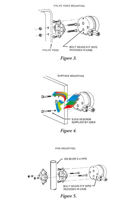
creasing output). When reinstalling the motor (Step 9 below), the exposed marking on the motor cover must indicate the desired action. 1. Disconnect instrument from installation (input wiring, air lines, and mounting bolts). 2. Remove two screws holding span bracket. SeeFigure 1212.
Figure 12.
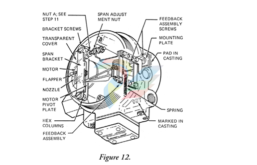
3. Remove two screws holding feedback assembly (with bellows). Note routing of tubing for later replacement.
NOTE
Do not remove mounting plate from feedback assembly. Remove as a unit.
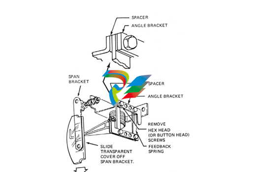
4. Lift aside feedback assembly (do not damage nozzle) to expose spring on bottom of case. Slide transparent cover off span bracket as shown inFigure 1313. Unhook spring from motor bracket.
(For convenience, feedback assembly can be removed entirely by disconnecting tubing. Note identification of tubing for later reconnection.)
10
MI 018-430– June 2005
5. On feedback assembly, remove two hex head (formerly buttonhead) screws. Interchange locations of angle bracket and spacer. SeeFigure 1313.
Reinstall hex head screws and tighten to a torque of 3.4 to 4.0 N•m (30 to 35 lb•in). Switching locations of angle bracket and spacer allows the Ni-Span angle bracket to correct for temperature induced errors in the INC-DEC mode.
Figure 13shows parts in INC-INC arrangement.
Figure 13.
6. Remove hex columns (use 5/16-inch wrench), and lift off motor pivot plate. SeeFigure 1212.
7. Lift out motor. Carefully lift flapper straight up from flapper arm on motor. Do not deform flapper. Holding on to flapper arm on other end of motor while removing will prevent internal motor flexure deformation.
8. Remove two screws holding bracket to bottom of motor. SeeFigure 1414. Invert motor and reinstall bracket (on side of motor that was formerly on top).
11
MI 018-430 – June 2005
Figure 14.
9. Wind excess wire clockwise around motor and carefully place motor into position in the case assuring that bottom arm is
-
Kollmorgen AKM54G-ANC2DB00 servo motor
-
Kollmorgen S200 Series S20350-VTS SERVO DRIVE
-
KOLLMORGEN AKD-P00606-NBCC-I000 SERVO DRIVE
-
Kollmorgen MV65WKS-CE310/22PB Servo Drive Control Module
-
Kollmorgen S20360-VTS-021 Servo Drive
-
KOLLMORGEN CR06550 High-precision digital servo amplifier
-
KOLLMORGEN DBL5N01050-03S-VV0-S40 Phase AC Synchronous Brushless Servo Motor
-
KOLLMORGEN S70301-NANANA-024 SERVO DRIVE
-
Kollmorgen S20360-VTS S200 Series Servo Drive
-
Kollmorgen RBE-03011-A00 Brushless Frameless Servo Motor
-
KOLLMORGEN AKD-T00306-NBAN-0000 INPUT SERVO DRIVE
-
KOLLMORGEN S700 Servo Controller S70302-NANANA
-
Kollmorgen AKD-P00607-NBEC-0000 400/480VAC 4.40KVA Servo Drive.
-
KOLLMORGEN S70102-NANANA SERVO DRIVE
-
KOLLMORGEN AKM21E-ANSNEH02 PM Servo Motor & PRD-AMPE25EB-00 Servo Drive Array
-
KollMorgen SC1R06260 Servo Drive 1.4/2.2 KVA 115230 Vac
-
Kollmorgen AKD-P00306-NBAN-0000 Servo Drive
-
Kollmorgen TTB2-2042-3052-A DC Motor Industrial Drive 5.5A 185 oz/inIntegrated safety
-
KOLLMORGEN SERVOSTAR 610-AS SERVO AMPLIFIER_SERVOSTAR610AS_S61001
-
KOLLMORGEN Seidel 60WKS-CE240/26PB 26A Servo Drive Module Control 60WKS-M240/26
-
KOLLMORGEN PRD-0016400P-10 & PRD-0016600D-30 Axis Control System Modules
-
KOLLMORGEN Seidel DBL5N01700-03S-000-S40 Servo Motor
-
HIRSCHMANN RS30-0802O6O6SDAP RAIL SWITCH
-
Hirschmann RS20-1600M2T1SDAEHH03.1.02 Rail Switch
-
Hirschmann RSPM20-4T14T1EV9HHS999.9.99 Managed Ethernet Switch
-
Hirschmann BELDEN RS40-0009CCCCSDAPHH09.0.14 / RS400009CCCCSDAPHH09014
-
Hirschmann RS40 Rail Switch RS40-0009CCCCSDAE
-
Hirschmann BELDEN RS30-0802T1T1SDAP / RS300802T1T1SDAP Fully Managed Layer 2 Compact Rail Switch
-
Hirschmann BELDEN RS20-0800M2M2SDAUHH / RS200800M2M2SDAUHH
-
Hirschmann EAGLE30-04022O6TT999SCCY9HSE3F Industrial Firewall Router Switch
-
Hirschmann RS20-1600T1T1SDAEHH09.0.14 RS20 Rail Mount Ethernet Switch
-
Hirschmann EAGLE 0200T1T1TDDY90000HHE05.3.03 Industrial Security Router
-
Hirschmann - BELDEN MIPP-AD-1L9P
-
HIRSCHMANN RSPM20-4Z64Z6TV9HHS9 942 106-999 RAIL SAFETY SWITCH
-
HIRSCHMANN FIBEROPTIC MODULE FIP P/N: OZDFIPG3 T
-
HIRSCHMANN RS20-1600M2M2SDAUHH Ethernet rack-mounted switch
-
BELDEN RS20-0400T1T1SDAEHH04.0.01 / RS200400T1T1SDAEHH04001
-
HIRSCHMANN MM2-4FXM3 MICE Media Module
-
Hirschmann RS20-2400T1T1SDAP / RS20-2400T1T1SDAPHH05.0.02
-
GE MLJ1005B010H00C MLJ Digital Synchromism Check
-
ALSTOM MICROTECH DX21-M2 Digital Excitation Controller
-
HIRSCHMANN BRS20-1200ZZZZ-STCY99HHSES
-
HIRSCHMANN MM3-4FXM2 MICE Media Module
-
Hirschmann RSB20-0800T1T1SAABHH 8Port ENet Rail Switch RSB20
-
Hirschmann MACH102-8TP Ethernet Switch
-
SAACKE DDZ-M marine steam pressure atomizer
-
SAACKE SKV-A marine rotary cup atomizer
-
SAACKE Seavis HMI05e
-
Kollmorgen MMC-SD-2.0-230 Servo Drive 100-240VAC 2KW 10A Output 3PH 100-240VAC
-
Kollmorgen Servo drive CR10550
-
Kollmorgen AKD-P01207-NACN-0054 Servo Driver
-
Kollmorgen S406M-CA-036 Servostar
-
Kollmorgen AKD-B02407-NAAN-0000 Digital Servo Drive
-
Kollmorgen SERVOSTAR S406AM-CA Digital Servo Drive
-
KOLLMORGEN SERVOSTAR 603-AS SERVO AMPLIFIER_SERVOSTAR603AS_S60301
-
Kollmorgen S700 Servo Controller (S70602-NANANA-NA)
-
Kollmorgen MPK411 controller
-
KOLLMORGEN MMC-SD-1.3-460-D Smart Drive
-
KOLLMORGEN AKM21C-CKB2AA-00 / AKM21CCKB2AA00 Servomotor
-
BECKHOFF AX5106-0000-0200 | Digital Compact Servo Drives 1-channel
-
BECKHOFF C3620-0000 INDUSTRIAL COMPUTER (MOTORSHELVES)
-
Beckhoff EK1960-0000 TwinSAFE Compact Controller
-
Beckhoff C6930-0050 Control Cabinet Industrial PC
-
Beckhoff CX1001-0111 Embedded PC CPU Module
-
Beckhoff C6017-0020 | Ultra-compact Industrial PC
-
Beckhoff EK1322 | 2-port EtherCAT P junction with feed-in
-
Beckhoff CP2219-0010 Panel
-
BECKHOFF C6015-0020 ULTRA COMPACT INDUSTRIAL PC
-
BECKHOFF CX2030-0120/Standard CPU Module Embedded PC Windows PLC controller
-
Beckhoff CP7721-1090-0020 Panel PC
-
Beckhoff PC CPU Module CX5130-0175
-
Beckhoff C6920-0050 Control Cabinet
-
Beckhoff EL6631 EtherCAT 2-Port Communication Interface, Profinet RT Controller
-
Beckhoff CP6202-0001-0060 touch screen panel PC
-
Beckhoff CP3916-1002-0000 Multi-Touch Control Panel
-
Beckhoff EP1809-0021 | EtherCAT Box, 16-channel digital input, 24 V DC, 3 ms, M8Preferred type
-
Beckhoff CX8190 PLC Embedded Industrial PC Ethernet Controller
-
Beckhoff CX2100-0914 Power Supply for External
-
Beckhoff Automation CP6906-0001-0000 HMI
-
Beckhoff EP7342-0002 Module
-
Beckhoff CX1020-0112 / CX1100-0910 / CX1020-N010 / CX1100-0003 Windows CPU
-
Beckhoff EP7211-0034 EtherCAT Box 1 Channel Motion Interface
-
Beckhoff C6240-0030 Control cabinet Industrial PC
-
beckhoff motherboard CB1052-0004 CB1052-0004
-
Beckhoff AX2006-AS Servo Drive / Variable Frequency Drive
-
BECKHOFF CP6207-0001-0020 NSMP
-
Beckhoff C6930-1142-0060 Industrial Computer
-
Beckhoff FC7501-0000 interface card
-
Beckhoff CX5140-0175 Embedded PC PLC CPU CX5140 Industrial Controller
-
Beckhoff CP7802-1100-0010 High-End IP65 Control Panel with DVI/USB Extended Interface
-
BECKHOFF CP3716-1058-0010 CONTROL PANEL
-
Beckhoff AX8108-0000 Single-Axis Module
-
Beckhoff CU8851-0000 | USB extension, USB Extended 2.0 receiver box
-
Beckhoff C6017-0030 | Ultra-compact Industrial PC
-
Beckhoff CX1001-0120/CX10010120.cx1000-n001.cx1000-n000 System Overview
-
Beckhoff CPU Module CX5140-0155/4GB CPU Module
-
Beckhoff CP6533-0001-005: Built-in Panel PC with High-Definition Multi-Touch Control
-
Beckhoff EL5042 | EtherCAT Terminal, 2-channel encoder interface, BiSS® C
-
Beckhoff C6920-1080-0040: Premium Control Cabinet Industrial PC
-
Beckhoff C6920-0060 | Control cabinet Industrial PC
-
Beckhoff Embedded-PC CX5010-1121
-
Beckhoff CB3050-0010 Mainboard Motherboard
-
Beckhoff PLC module CX1020-0000
-
Beckhoff Compact Servo Amplifier AX5112-0000-0200
-
Beckhoff CP7812-1056-0010 15" Multitouch Display Control Panel
-
Beckhoff CX5120-0115 /2GB Controller Module
-
Beckhoff CP7201-1000-0000 Industrial Panel PC
-
Beckhoff Servo Motor AM8061-0JH1-0000
-
BECKHOFF CP6503-0001-0050 Built-in Panel PC
-
Beckhoff CP3919-0010 Display G190ETN01.2 19" PCT V04. Multi-touch Control Panel
-
Beckhoff CX5110-0112-9020/000368201 Embedded PC Intel Atom Processor
-
Beckhoff AX8206-0000-0000 | Dual-axis module
-
Beckhoff Nail Operating Terminal CP7032-1031-0010
-
Beckhoff AM8042-0EH1-0000 Servomotor 4.10 Nm (M0), F4 (87 mm)
-
Beckhoff EK9300 | PROFINET RT Bus Coupler
-
Beckhoff CP3224-0020 Multitouch-Panel-PC
-
Beckhoff CP2712-0000 12.1" 24VDC Touch Screen WMD0
-
BECKHOFF CX5240-0195 / 0000289234 Embedded PC 40 GB CFast Card
-
Beckhoff CP6932-1000-0000 Control Panel
-
BECKHOFF CX5120-0121 PLC Module
-
Beckhoff EL3218 | EtherCAT Terminal, 8-channel analog input
-
Beckhoff EL3218 | EtherCAT Terminal, 8-channel analog input
-
Beckhoff C6640-0050 | Control cabinet Industrial PC
-
Beckhoff Cx5130-0120/4GB Embedded-PC
-
BECKHOFF CX2030-0122 PLC PROCESSOR
-
BECKHOFF CX5020-0122 Controller Module
-
Beckhoff CP3915-0000 Multitouch Panel
-
BECKHOFF EL3014 | EtherCAT Terminal
Add: High-tech Software Park, Xiamen City, Fujian Province
Mobile: +86-17750019513(WhatsApp)
Email: yy4291644@gmail.com
Website: https://www.abb-sis.com
.jpg)
.jpg)
.jpg)
.jpg)
.jpg)
.jpg)

-
Kollmorgen AKM54G-ANC2DB00 servo motor
-
Kollmorgen S200 Series S20350-VTS SERVO DRIVE
-
KOLLMORGEN AKD-P00606-NBCC-I000 SERVO DRIVE
-
Kollmorgen MV65WKS-CE310/22PB Servo Drive Control Module
-
Kollmorgen S20360-VTS-021 Servo Drive
