

Woodward 723PLUS Digital Control
attenuation of the RF signals from the control can be guaranteed, no additional
special measures are needed. The signals in the 156–165 MHz range must be
attenuated by 6 dB before they reach the receiver antenna or receiver
(interference point), and the control must be >3 m away from the antenna or
receiver. This is a specific installation dependency, and some examples may
include:
A grounded, metal, IP rated cabinet with all cabling staying inside it for more
than 2 m length, with any shield terminations at the cabinet exit/entry point
and all unshielded cable routed directly against the metal cabinet.
A below-deck metal engine room where none of the cabling, including power,
leaves the engine room.
If using a specific installation location or method as a means to meet the Marine
Notch requirements, instead of a secondary metal shield for cabling, consult the
ship builder. Acceptability of the installation for obtaining 6 dB of RF attenuation
in the 156–165 MHz range must be provided by the ship builder. Woodward will
not know the ship installation application or requirements to provide guidance.
Internal Jumpers
The 723PLUS control has ten, two-position internal jumpers (JPR1 through
JPR20) located on the top of the printed circuit board. If it is necessary to change
any jumper to match your control requirements, and this suits the nature of the
software, be sure to read page v, Electrostatic Discharge Awareness.
Remove power and all inputs. Wait 45 seconds, then remove cover. With your
fingers or a small pair of tweezers, carefully remove the appropriate jumper and
replace it securely over the proper two connectors (see Figure 2-1).
Notes for Figure 2-2
Shielded wires are twisted pairs, with shield grounded at one end only. When
mounting control to bulkhead, use the grounding stud and hardware supplied with
the chassis to ensure proper grounding.
Shields must not be grounded at any external point unless otherwise noted.
All shields must be carried continuously through all terminal blocks and must not be
tied to other shields except at the common ground point. Tie all shields together at
ground stud located near connector J1.
Remove jumper for voltage input.
Remove jumper if using external discrete input power.
Discrete inputs are isolated from other circuits and intended to be powered by
TB1-39 (+24) leaving the jumper in place. Input current is nominally 10 mA input into
2210 Ω.
7. Unless otherwise specified:
A. Relays shown de-energized
B. Relays energize for function
C. Relay contact ratings for minimum 100 000 operations:
Resistive— 2.0 A at 28 Vdc
0.1 A at 115 Vac 50 to 400 Hz
Inductive— 0.75 A at 28 Vdc 0.2 Henry
0.1 A at 28 Vdc lamp
Analog output signals to other systems must be isolated from ground either by
design or employment of isolation amplifiers.
Analog input signals to other systems must be isolated from ground either by design
or employment of isolation amplifiers.
10. Factory set for MPU input.
11. Factory set for 20–160 mA output.
12. Factory set for 4–20 mA output.
13. Internal power supply provides dc isolation between the power source and all other
inputs and outputs.
14. Communication port J1 can be used with the Woodward ST2000 Hand Held
Programmer or PC Interface using Watch Window/Servlink software.
15. Communication port J2 or J3 can be configured as an RS-232. RS-422. or RS-485
serial interface. Port configuration can be done in the application software only. For
the pin assignment of J2 and J3. see later in this chapter.
16. This analog output may connect to a metering/controlling device. The shield should
be continuous between all connected devices with a single shield termination point to
ground.
17. Use twisted pair shielded wires only.
18. Remove jumper if used with the gas engine I/O node.
Termination is accomplished using a three-resistor voltage divider between a
positive voltage and ground. The impedance of the resistor network should be
equal to the characteristic impedance of the cable. This is usually about 100 to
120 ohms. The purpose is to maintain a voltage level between the two differential
lines so that the receiver will be in a stable condition. The differential voltage can
range between 0.2 and 6 volts; but the maximum voltage between either receiver
input and circuit ground must be less than 10 volts. There is one termination
resistor network for each port located on the 723PLUS board. Connection to this
resistor network is made through the 9-pin connectors on pins 6 and 9. See
Figures 2-5 through 2-8 for termination and cable connection examples.
Due to the variety of installations, plus system and component tolerances, the
723PLUS control must be tuned to each system for optimum performance.
This chapter contains information on how to enter control set points through the
control's menu system using the Hand Held Programmer. If you have access to
the Watch Window software tool and Servlink software, you can set up and tune
the 723PLUS control from a PC (personal computer) using the instructions in
Chapter 5 of this manual.
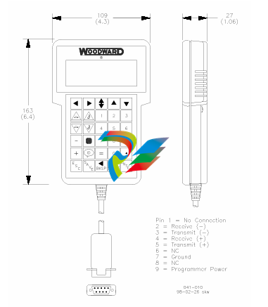
Hand Held Programmer and Menus
The Hand Held Programmer is a hand-held computer terminal that gets its power
from the 723PLUS control. The terminal connects to the RS-422 communication
-
CTI 2512 75-Watt AC/DC Power Supply
-
CTI 2510 125 VDC Power Supply
-
CTI 2500-SSB Single Slot Blank Front Panel
-
CTI 2500-R11-A Eleven-Slot Redundant Base
-
CTI 2500P-R16 Sixteen-Slot Base with High-Speed Channel
-
CTI 2500P-R8 Eight-Slot Base with High-Speed Channel
-
CTI 2500P-R4 Four-Slot Base with High-Speed Channel
-
CTI 2541 Redundant Processor Manager Module
-
CTI 2577 Profibus DP Slave Adapter
-
CTI 2573-MOD Serial Interface Adapter with MODBUS
-
CTI 2572-AF Fast Ethernet TCP/IP Adapter with Optical Fiber Connection
-
CTI 2572-A Fast Ethernet TCP/IP Adapter
-
CTI 2572 Ethernet TCP/IP Adapter
-
CTI 2572-B Fast Ethernet TCP/IP Adapter
-
CTI 2576 DeviceNet™ Scanner Module (MATURE)
-
CTI 2500P-ECC1 Ethernet Communications Coprocessor
-
CTI 2500P-JACP Janus Application Coprocessor
-
CTI 2500P-ACP1 Application Coprocessor (MATURE - replaced by 2500P-JACP)
-
CTI 2500P-J450 Janus PAC with 2MB Project Memory
-
CTI 2500-C400 CPU with 3072K User Memory
-
CTI 2500-C300 CPU with 512K User Memory
-
CTI 2500-C200 CPU with 256K User Memory
-
CTI 2500-C100 CPU with 128K User Memory
-
CTI 2500P-J750 Janus PAC with 3MB Project Memory
-
Shinkawa WHF3006M Displacement Converter
-
Shinkawa JBP-220 (P-24-94A / P-24-94B) Circuit Board Module
-
SHINKAWA WKN-142K5 2-WIRE VIBRATION TRANSDUCER
-
Shinkawa FRP-321 (P-26-54A / P-26-54B) Circuit Board Module
-
Shinkawa IOP-160 (P-25-72A / P-25-72B) Circuit Board Module
-
Shinkawa PK-147B-1 / PK-147A-1 Circuit Board Module
-
Shinkawa CPP-91A Circuit Board Module
-
Shinkawa FRP-177 PCB Module
-
Shinkawa CPP-127 (P-26-74A / P-26-74B) Circuit Board Module
-
Shinkawa FRP-227 (P-24-86A / P-24-86B) Circuit Board Module
-
Shinkawa MDP-104 (P-25-83A / P-25-83B) Circuit Board Controller
-
Shinkawa VK-143P2 High-precision eddy current sensor driver/signal conditioner
-
Shinkawa FRP-226 (P-24-86A / P-24-86B) Circuit Board Module
-
Shinkawa CPP-107A P-22-99A P-22-99B Circuit Board Module
-
SHINKAWA VW-202AL-8 Axial Displacement Sensor
-
Shinkawa VL-202A08L-1A42 Vibration Sensor Transducer Probe
-
Shinkawa FRP-209A & FRP-206 Wire Bonder Circuit Board Module
-
Shinkawa MGP-72 MGP72 P-26-50A P-26-50B Circuit Board Module
-
Shinkawa FRP-249 P-25-1A P-25-1B Circuit Board Module
-
Shinkawa FRP-320 P-26-54A P-26-54B Circuit Board Module
-
Shinkawa FRP-282 P-24-35A P-24-35B Circuit Board Module
-
Shinkawa FRP-338 P-26-54A P-26-54B Circuit Board Module
-
GE IS200AEPBH1B Pitch-Charger Control PCB Board
-
GE IS200EDEXG1ADA EX2100 SCR Trigger Control Board
-
GE 151X1207CK01SA01 IS200EDEXG1A EX2100 SCR
-
GE 151X1233DD02SA02 IS200AEPBH1B - Variant for pitch control charger assembly
-
GE 151X1233DB01SA01 IS200AEPBH1B - 10kW Wind Power Converter
-
GE 151X1233DB01SA01 IS200AEPBH1B - 10kW Wind Power Converter
-
GE 151X1233DB01SA01R | IS200AEPBH1B 10KW Converter
-
GE 151X1233DD01SA02 Pitch Battery Charger (109W6931P001)
-
GE 151X1233DD01SA02 Pitch Battery Charger Assy IS200AEPBH1B
-
GE 151X1233DB02SA02 Rev A IS200AEPBH1B Wind Turbine Converter
-
GE 151X1207CK02SA02 SCR 4400 V 1850 A IS200EDEXG1ADA General Electric EX2100
-
Triconex 3723X 32-Channel TMR Analog Input Module with HART
-
SHINKAWA VM-21G SIGNAL CONDITIONER SOCKET
-
SHINKAWA VM-21R REVOLUTION SIGNAL CONDITIONER
-
SHINKAWA VM-21T DISPLACEMENT INPUT THRUST SIGNAL CONDITIONER
-
SHINKAWA VM-21D 6-WIRE LVDT SIGNAL CONDITIONER
-
SHINKAWA VM-21P 3-WIRE LVDT SIGNAL CONDITIONER
-
SHINKAWA VM-21A VIBRATION SIGNAL CONDITIONER
-
SHINKAWA VM-21K DISPLACEMENT INPUT VIBRATION SIGNAL CONDITIONER
-
SHINKAWA VM-25S01 CONDITION MONITORING SYSTEM
-
SHINKAWA VM-25 CONDITION MONITORING SYSTEM
-
SHINKAWA VM-772B DEVICE CONFIG
-
SHINKAWA VM-771B MCL VIEW
-
SHINKAWA VM-76B INSTRUMENT RACK
-
SHINKAWA VM-75B POWER SUPPLY MODULE
-
SHINKAWA VM-742B NETWORK COMMUNICATION MODULE
-
SHINKAWA VM-741B LOCAL COMMUNICATION & PHASE MARKER MODULE
-
SHINKAWA VM-722B 9-CHANNEL RELAY MODULE
-
SHINKAWA VM-707B AERODERIVATIVE GAS TURBINE MONITOR MODULE
-
SHINKAWA VM-706B ROD DROP MONITOR MODULE
-
SHINKAWA VM-705B 18-CHANNEL TEMPERATURE MONITOR MODULE
-
SHINKAWA VM-704B TEMPERATURE MONITOR MODULE
-
SHINKAWA VM-703B TACHOMETER & ECCENTRICITY MONITOR MODULE
-
SHINKAWA VM-702B ABSOLUTE VIBRATION MONITOR MODULE
-
SHINKAWA VM-701B VIBRATION / DISPLACEMENT MONITOR MODULE
-
SHINKAWA MODEL VM-5X INTERFACE UNIT
-
SHINKAWA MODEL VM-5W2 DUAL POWER SUPPLY INSTRUMENT RACK
-
SHINKAWA MODEL VM-5H4 INSTRUMENT RACK (for VM-5Z5.6.7)
-
SHINKAWA MODEL VM-5G SINGLE UNIT INSTRUMENT RACK
-
SHINKAWA MODEL VM-5Z5,6,7 POWER SUPPLY UNIT
-
SHINKAWA MODEL VM-5Y1,2,3 RELAY MODULE UNIT
-
SHINKAWA MODEL VM-5P3 PHASE MARKER UNIT
-
SHINKAWA MODEL VM-53 DUAL COMMUNICATION UNIT
-
SHINKAWA MODEL VM-52 BOTTOM HOLD MONITOR
-
SHINKAWA MODEL VM-51 ROD DROP MONITOR
-
SHINKAWA MODEL VM-5R TACHOMETER
-
SHINKAWA MODEL VM-5S DUAL TACHOMETER
-
SHINKAWA MODEL VM-5A DUAL VALVE
-
SHINKAWA MODEL VM-5E DUAL CASE
-
SHINKAWA MODEL VM-5L COMPLEMENTARY INPUT
-
SHINKAWA MODEL VM-5N RAMP DIFFERENTIAL
-
SHINKAWA MODEL VM-5D DUAL DIFFERENTIAL
-
SHINKAWA MODEL VM-5T DUAL THRUST MONITOR
-
SHINKAWA MODEL VM-5C ECCENTRICITY MONITOR
-
SHINKAWA MODEL VM-5C ECCENTRICITY MONITOR
-
SHINKAWA MODEL VM-5M DUAL PATH MONITOR
-
SHINKAWA MODEL VM-5B DUAL ACCELERATION MONITOR
-
SHINKAWA MODEL VM-5B DUAL ACCELERATION MONITOR
-
SHINKAWA MODEL VM-5U DUAL SEISMIC MONITOR
-
SHINKAWA MODEL VM-55 VIBRATION MONITOR
-
SHINKAWA VM-742B1-5 VIBRATION MONITORING SYSTEM CARD
-
Shinkawa PSP-17B P-24-64A P-24-64B Circuit Board Module
-
SHINKAWA MGP-67 PCB
-
Shinkawa JBP-278 P-22-48A-1 P-22-48B-1 Circuit Board Module
-
Shinkawa VM-721B 18-CHANNEL RELAY MODULE
-
Shinkawa FRP-337 P-26-54A P-26-54B Circuit Board Module
-
Shinkawa WKN-142K2-2 Vibration Transmitter
-
SHINKAWA VL-202A08L-1012 Rotor Position Monitor Probe Sensor
-
Shinkawa CPP-128 P-26-74A P-26-74B Circuit Board Module
-
Honeywell 51402755-100 PROCESSOR CARD
-
Honeywell 51107595-100 Power
-
HONEYWELL 51304544-100 Control Board
-
HONEYWELL 51109919-100 BOARD
-
HHoneywell 51204160-175 Digital Input Module
-
Honeywell 51304754-150 High Level Analog Input Module
-
HONEYWELL 51304690-100 DIGITAL INPUT CARD
-
Honeywell 51401635-150 COMM CONTROL
-
HONEYWELL 51204174-175 MC-TAOY 52 ANALOG OUTPUT BOARD
-
HONEYWELL 51400596-100
-
HONEYWELL 51401291-100 board card
-
HONEYWELL 51401642-150 I/O LINK MODULE
-
Honeywell LCN‑E Hub Power Supply 38500148‑300

Add: High-tech Software Park, Xiamen City, Fujian Province
Mobile: +86-17750019513(WhatsApp)
Email: yy4291644@gmail.com
Website: https://www.abb-sis.com
.jpg)
.jpg)
.jpg)
.jpg)
.jpg)
.jpg)

-
CTI 2512 75-Watt AC/DC Power Supply
-
CTI 2510 125 VDC Power Supply
-
CTI 2500-SSB Single Slot Blank Front Panel
-
CTI 2500-R11-A Eleven-Slot Redundant Base
-
CTI 2500P-R16 Sixteen-Slot Base with High-Speed Channel
