


- Stucke Elektronik
- Kongsberg
- Abaco
- LAMBDA
- LAND
- Phoenix
- AMAT
- METSO
- SAMSUNG
- LEYBELOD
- SST
- IBA
- EMERSON
- NI
- SAMSUNG
- Moore
- Autronica
- Sieger
- Pacific Scientific
- ALFA LAVAL
- Others
- 其他
- OMRON
- UNIOP
- AMAT
- ICS Triplex
- Lam Research
- KUKA
- Hirschmann
- ELAU
- EATON
- Applicom
- Watlow Anafaze
- Meggitt Vibro-meter
- Carrier
- Other
- ROCKWELL
- Rolls-Royce
- SAACKE
- Yokogawa
- B&R
- Reliance Electric
- Seifert
- A-B
- Weimeide Metso
- KEBA
- HIMatrix
- Valmet
- Schneider
- Prosoft
- PEPPERL+FUCHS
- Honeywell
- Woodward
- GE
- GEA Westfalia Separator
- Bently Nevada
- ALSTOM
- Foxboro
- MOTOROLA
- Fanuc
- VMIC
- KOLLMORGEN
- SEW
- Rexroth
- AEROTECH
- TOSHIBA
- TmeIC
- Sumitomo
- SOCAPEL SOCASIN
- SMC
- Stromag
- SIEMENS
- SCHUMACHER
- ABB
- MOOG
- EPRO
- EMERSON
- Triconex
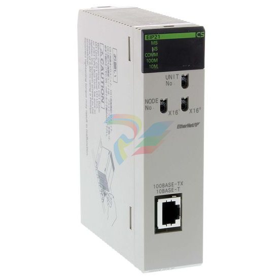
OMRON CS1W-EIP21 PLC
OMRON CS1W-EIP21 PLC
The bits in the ranges shown below have specific functions, but can still be used
as work bits when their specific functions are not being used.
Range
IR 096 to IR 099
Function
When the MACRO instruction is used, these bits serve as op
erand input bits.
IR 196 to IR 199
When the MACRO instruction is used, these bits serve as op
erand output bits.
IR 230 to IR 231
When high-speed counter is used, these bits are used to store
its present value.
LR 00 to LR 63 are used as link bits, but they can also be used as work bits when
not linked to another ID Controller. Refer to the CQM1 Programming Manual for
details on using link bits in 1-to-1 communications.
These bits mainly serve as flags related to ID Controller operation. For details on
the various bit functions, refer to Appendix D AR and SR Area Allocations.
SR 244 to SR 247 can also be used as work bits, when input interrupts are not
used in Counter Mode.
When a complex ladder diagram cannot be programmed in mnemonic code just
as it is, these bits are used to temporarily store ON/OFF execution conditions at
program branches. They are used only for mnemonic code. When programming
directly with ladder diagrams using the Ladder Support Software (LSS) or SYS
MAC Support Software (SSS), TR bits are automatically processed for you.
The same TR bits cannot be used more than once within the same instruction
block, but can be used again in different instruction blocks. The ON/OFF status
of TR bits cannot be monitored from a Peripheral Device.
These bits retain their ON/OFF status even after the ID Controller power supply
has been turned off or when operation begins or stops. They are used in the
same way as work bits.
| 1768-PA3 Allen Bradley CompactLogix Power Supply |
| VE4001S2T2B7 EMERSON Discrete Input Card |
| MPL-B580J-SJ22AA Allen Bradley Premium permanent magnet rotary servo motor |
| SST-PB3-PCIE-2 PROFIBUS Interface PCI Card Molex |
| 330103-00-07-50-02-05 Bently Nevada 3300 XL 8 mm Probe |
| VT-VPCD-1-1X/V0/1-0-1 REXROTH Electronic signal amplifier |
| 810-186753-002 PCB Indexer Interface LAM 810-800081-022 |
| 2711P-PR8DK Allen Bradley PanelView Plus 6 Operator Terminal |
| 2711P-K4M20D8 Allen Bradley Panelview Plus 6 400 Operator Terminal |
| PXle-8133 NI Embedded Controller for PXI and CompactPCI |
| MC07B0030-5A3-4-00 MKD Synchronous Motors REXROTH |
| 1756-IRT6I Allen-Bradley ControlLogix analog input module |
| 810-141735-005 PCB Indexer Interface LAM |
| ADV551-P60/D5S00 YOKOGAWA Digital Input Modules |
| ADV151-P60/B5S00 YOKOGAWA Digital Input Modules |
| MTL4544S MTL ISOLATING DRIVER |
| MTL4546Y MTL ISOLATING DRIVER |
| A02B-0333-C263 FANUC Robot teaching device |
These bits mainly serve as flags related to ID Controller operation. For details on
the various bit functions, refer to relevant sections in this manual or to Appen
dix D AR and SR Area Allocations.
When the ID Controller is linked one to one with another ID Controller, these bits
are used to share data. Refer to the CQM1 Programming Manual for details on
using link bits in 1-to-1 communications.
LR bits can be used as work bits when not used for data links.
Timers/Counters Area
This area is used to manage timers and counters created with TIM, TIMH(15),
CNT, and CNTR(12). The same numbers are used for both timers and counters
and each number can be used only once in the user program. Do not use the
same TC number twice even for different instructions.
TC number are used to create timers and counters, as well as to access Comple
tion Flags and present values (PVs). If a TC number is designated for word data,
it will access the present value (PV); if it is used for bit data, it access the Comple
tion Flag for the timer/counter.
The Completion Flag turns ON when the PV of the timer/counter that is being
used goes to 0.
Refer to the CQM1 Programming Manual for details on timers and counters.
Note 1. TC numbers 000 through 015 and interrupt processing should be used for
TIMH(15) whenever the cycle time is longer than 10 ms. Using other timer/
counter numbers or not using interrupt processing will lead to inaccuracy in
the high-speed timers. Interrupt processing can be set in DM 6629 of the ID
Controller Setup.
2. When the input condition turns OFF for TIM or TIMH(15), the PV is reset and
returns to the set value. The PV is also reset at the beginning of program
execution or when the interlock condition goes OFF in a interlocked pro
gram section (IL–ILC). The PV for CNT or CNTR(12) is not reset like one for
the timer instruction, but rather is reset only when the reset input goes ON
| User name | Member Level | Quantity | Specification | Purchase Date |
|---|


-
ABB PFSA107-Z42 DTU Stressometer Digital Transmission Unit
-
Nidec Mentor MP
-
IBA PC connection for high-precision data acquisition with ibaNet-E
-
IBA FO Connection to Reflective Memory
-
IBA FO Connection to Siemens Systems
-
IBA Interface Cards For Fiber Optic Connections
-
IBA Field and Drive Buses
-
IBA ibaPADU-S Modular System
-
IBA ibaMAQS
-
STUCKE SYMAP®ARC
-
STUCKE SYMAP®R
-
STUCKE SYMAP®Compact
-
MOOG G123-825-001 BUFFER AMPLIFIER
-
Motorola MVME5100 Series VME Processor Modules
-
ABB MEASUREMENT & ANALYTICS NGC8209 Natural gas chromatograph
-
Motorola MVME162 Embedded Controller
-
HIMatrix Safety-Related Controller System Manual for the Modular Systems
-
MOTOROLA MVME2400 Series VME Processor Module
-
Sieger System 57
-
KONGSBERG MRU product line continuation
-
Woodward easYgen-3100/3200 Genset Control for Multiple Unit Operation
-
Woodward MFR 300 Multifunction Relay / Measuring
-
ABB AX410, AX411, AX416, AX450 and AX455 Single and dual input analyzers
-
Woodward easYgen-1400 Technical Manual Genset Control
-
Woodward easYgen-400 Operation Manual Genset Control
-
Woodward High Output Digital Valve Positioner (DVP) DVP5000/DVP10000/DVP12000
-
Woodward High Output Digital Valve Positioner DVP5000 and DVP10000
-
Woodward TG611-13/-17 Overspeed Test Device Conversion Kit
-
Woodward MicroNet Safety Module (MSM)
-
Woodward 2301A Electronic Load Sharing and Speed Control 9905/9907 Series
-
Woodward-Service Bulletin 01671
-
UniOP eTOP40B 12.1” TFT color display
-
UniOP eTOP40 TFT Color display
-
UniOP eTOP33B 10.4” TFT color display
-
UniOP eTOP33C eTOP33-0050 Resistive touchscreen
-
UniOP eTOP30. eTOP32 eTOP32-0050 Human-machine interface equipment
-
UniOP eTOP20B and eTOP21B eTOP20B-0050
-
UniOP eTOP12 eTOP12-0050 Advanced human-machine interface equipment
-
UniOP eTOP11 eTOP11-0050 HMI
-
UniOP eTOP06 HMI
-
UniOP eTOP05EB eTOP05EB-DF45 HMI
-
UniOP eTOP05. eTOP05P Human-machine interface equipment
-
UniOP eTOP03 eTOP03-0046
-
UniOP eTOP507 507U2P1 eTOP Series 500 Human-Machine Interface
-
UniOP eTOP307
-
UniOP ePAD32B, ePAD33B and ePAD33BT ePAD33B-0350
-
UniOP ePAD05 and ePAD06
-
UniOP ePAD04 ePAD04-D046 Universal Operator Panel
-
UniOP ePAD03 and ePAD04
-
UniOP CP02F-02, CP02R-04
-
UniOP CP01R-04 Compact Human-Interface Device
-
UniOP ERT-16 - Industrial PLC Workstation
-
UniOP ePAD03 and ePAD04
-
UNIOP EPALM10-DA71 state-of-the-art handheld HMI
-
Watlow SERIES CLS200 SPECIFICATION SHEET
-
Detailed Explanation of B&R Power Panel 300/400: The Core of Industrial Automation Control
-
YOKOGAWA Models ANB10S, ANB10D, ANR10S, ANR10D Node Units (for FIO)
-
Woodward ESDR 4 Current Differential Protection Relay
-
Woodward easYgen-3000 Genset Control for
-
Woodward CPC-II Current-to-Pressure Converter
-
Woodward 8290-189-EPG-installation-manual 8290-044
-
Woodward Product Change Notification 06946A
-
Woodward Product Change Notification 06912
-
Fisher™ 4660 High-Low Pressure Pilot
-
Flexible digital protection and control equipment SYMAP®
-
Woodward 723PLUS Digital Control
-
Woodward 505 Digital Controller For steam turbineses
-
Woodward 85018V2 505E Digital Governor for Extraction Steam Turbines
-
Woodward 85018V1 Turbine Control Parameters
-
Woodward 26871 505 Enhanced Digital Control for Steam Turbines
-
Woodward 03365 505E (Extraction / Admission)
-
KONGSBERG RMP420-Remote Multipurpose Input/Output
-
KONGSBERG RCU501 Remote Controller Unit
-
KONGSBERG RCU500 Remote Controller Unit
-
K-Gauge TOP KONGSBERG Tank Overfill Protection SystemFeatures
-
Kongsberg DPS112 DGNSS (DGPS/DGLONASS) sensor
-
Kongsberg d0000930 presafe-atex-report signed
-
HIMax TECHNICAL FACTS X Series
-
GE Multilin F650
-
GE MIF II - Legacy
-
GE PQM II Power QualIty Meter
-
Hydran 201Ti Mark IV Essential DGA monitoring for transformers
-
alstom AMS42/84 5B Amplifier SystemAmplifier Technology at its Best.
-
GE VMIVME-5576 Fiber-Optic Reflective Memory with Interrupts
-
GE Multilin 750/760 - Legacy Feeder Protection System
-
GE Fanuc Automation VMICPCI-7806 Specifications
-
GE VMIVME-7807 VME-7807RC* Intel® Pentium® M-Based VME SBC
-
GE Fanuc Automation VMIVME-7750 Specifications
-
FOXBORO Compact FBM240. Redundant with Readback, Discrete
-
FOXBORO FBM208/b, Redundant with Readback, 0 to 20 mA I/O Module
-
FOXBORO FBM201e Analog Input (0 to 20 mA) Interface Modules
-
Foxboro DCS FBM206 Pulse Input Module
-
FOXBORO FBM216 HART® Communication Redundant Input Interface Module
-
FOXBORO Z-Module Control Processor 270 (ZCP270)
-
Foxboro DCS Compact FBM241/c/d, Redundant, Discrete I/O Modules
-
Foxboro FBM223 PROFIBUS-DP™ Communication Interface Module
-
Foxboro DCS FBM204. 0 to 20 mAI/OModule
-
Foxboro FBM239, Discrete 16DI/16DO Module
-
Foxboro FBM202 Thermocouple/mV Input Module
-
Foxboro E69F Current-to-Pneumatic Signal Converter
-
EMERSON M-series Intrinsically Safe I/O
-
Configuration for AMS 6500 Protection Monitors
-
EMERSON DeltaV™ M-series Traditional I/O
-
EMERSON DeltaV™ SQ Controller
-
AEROTECH Ndrive MP Hardware Manual
-
AEROTECH Ndrive HPe 10/20/30
-
AEROTECH Ndrive CP Hardware Manual
-
AEROTECH Ndrive Linear Series Digital Servo Amplifiers – Linear
-
AEROTECH Ndrive HP 10/20/30 P/N: EDU170
-
AEROTECH EDU176_Ndrive_HL
-
ADVANCEDMOTION CONTROLS Analog Servo Drive 120A10
-
GE JPAX-H
-
GE JPAX family
-
GE Industry Leading Experience
-
GE Ether-1000 Unit
-
GE Cyber Secured Service Unit
-
GE Lentronics E1MXe Multiplexer
-
GE TTMX Teleprotection Terminal
-
GE Lentronics T1 Multiplexer
-
GE Lentronics JungleMUX SONET Multiplexer
-
GE Lentronics E1MX Multiplexer
-
GE Lentronics TN1Ue SDH Multiplexer
-
GE Lentronics TN1U SDH Multiplexer
-
GE Gridcom DXC Family Access and Transmission Multiplexer
-
GE Advanced Network Management
-
GE Lentronics VistaNET Network Management System (NMS)
-
ABB System Controller Connect
-
Ethernet Module EI 803F ABB
Add: High-tech Software Park, Xiamen City, Fujian Province
Mobile: +86-17750019513(WhatsApp)
Email: yy4291644@gmail.com
Website: https://www.abb-sis.com
.jpg)
.jpg)
.jpg)
.jpg)
.jpg)
.jpg)

-
OMRON CQM1H-CPU61 PLC
-
OMRON CQM1H-MAB42 PLC
-
OMRON CS1G-CPU44-EV1 PLC
-
OMRON CS1G-CPU44H CPU
-
OMRON CS1H-CPU63-EV1 PLC
