


- Stucke Elektronik
- Kongsberg
- Abaco
- LAMBDA
- LAND
- Phoenix
- AMAT
- METSO
- SAMSUNG
- LEYBELOD
- SST
- IBA
- EMERSON
- NI
- SAMSUNG
- Moore
- Autronica
- Sieger
- Pacific Scientific
- ALFA LAVAL
- Others
- 其他
- OMRON
- UNIOP
- AMAT
- ICS Triplex
- Lam Research
- KUKA
- Hirschmann
- ELAU
- EATON
- Applicom
- Watlow Anafaze
- Meggitt Vibro-meter
- Carrier
- Other
- ROCKWELL
- Rolls-Royce
- SAACKE
- Yokogawa
- B&R
- Reliance Electric
- Seifert
- A-B
- Weimeide Metso
- KEBA
- HIMatrix
- Valmet
- Schneider
- Prosoft
- PEPPERL+FUCHS
- Honeywell
- Woodward
- GE
- GEA Westfalia Separator
- Bently Nevada
- ALSTOM
- Foxboro
- MOTOROLA
- Fanuc
- VMIC
- KOLLMORGEN
- SEW
- Rexroth
- AEROTECH
- TOSHIBA
- TmeIC
- Sumitomo
- SOCAPEL SOCASIN
- SMC
- Stromag
- SIEMENS
- SCHUMACHER
- ABB
- MOOG
- EPRO
- EMERSON
- Triconex
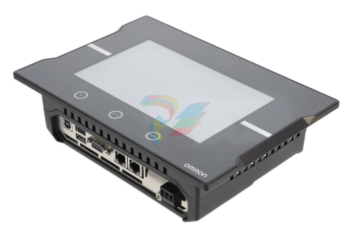
OMRON NA5-7W001B-V1 NA5-7W001S-V1 NA5-9W001B-V1 NA5-12W101B-V1 touch screen
OMRON NA5-7W001B-V1 NA5-7W001S-V1 NA5-9W001B-V1 NA5-12W101B-V1 touch screen
Touch screen HMI, 7 inch wide screen, TFT LCD, 24bit color, 800x480 resolution, frame color : Black
Specifications
Interaction Touch screen
Display Color graphics
HMI type Dedicated Advanced HMI
Display size and type 7 inch TFT Color LCD
Resolution 800 x 480
Memory size 900 MB
Bezel color Black
Characteristics
*1.The indication accuracy of K thermocouples in the −200 to 1.300°C range, T and N thermocouples at a temperature of −100°C max., and U
and L thermocouples at any temperature is ±2°C ±1 digit max. The indication accuracy of B thermocouples at a temperature of 400°C max. is
not specified. The indication accuracy of B thermocouples at a temperature of 400 to 800°C is ±3°C max.
The indication accuracy of R and S thermocouples at a temperature of 200°C max. is ±3°C ±1 digit max. The indication accuracy of C/W
thermocouples is (±0.3% of PV or ±3°C, whichever is greater) ±1 digit max.
The indication accuracy of PLII thermocouples is (±0.3% of PV or ±2°C, whichever is greater) ±1 digit max.
*2.However, the precision between 0 and 4 mA for a 0 to 20 mA output is ±1% FS max.
*3.Ambient temperature: −10°C to 23°C to 55°C, Voltage range: −15% to 10% of rated voltage
*4.K thermocouple at −100°C max.: ±10°C max.
*5.The unit is determined by the setting of the Integral/Derivative Time Unit parameter.
*6.External serial communications (RS-485) and USB-Serial Conversion Cable communications can be used at the same time.
*7.Refer to your OMRON website for the most recent information on applicable models.
*8.Refer to information on maritime standards in Shipping Standards on page124 for compliance with Lloyd's Standards.
*9.Industrial electromagnetic environment (EN/IEC 61326-1 Table 2)
Indication accuracy
(when mounted individually,
ambient temperature of 23°C)
Thermocouple: (±0.3 % of indication value or ±1°C, whichever is greater) ±1 digit max.*1
Platinum resistance thermometer: (±0.2 % of indication value or ±0.8°C, whichever is greater) ±1 digit max.
Analog input: ±0.2% FS ±1 digit max.
CT input: ±5% FS ±1 digit max.
Simple transfer output accuracy ±0.3% FS max.*2
Influence of temperature *3 Thermocouple input (R, S, B, C/W, PL II): (±1% of indication value or ±10°C, whichever is greater) ±1 digit max.
Other thermocouple input: (±1% of indication value or ±4°C, whichever is greater) ±1 digit max. *4
Platinum resistance thermometer: (±1% of indication value or ±2°C, whichever is greater) ±1 digit max.
Analog input: ±1% FS ±1 digit max.
CT input: ±5% FS ±1 digit max.
Influence of voltage *3
Influence of EMS. (at EN 61326-1)
Installation influence (E5DC only) R, S, B, W, or PLII thermocouple: (±1% of PV or ±10°C, whichever is greater) ±1 digit max.
Other thermocouple: (±1% of PV or ±4°C, whichever is greater) ±1 digit max. *4
Input sampling period 50 ms
Hysteresis Temperature input: 0.1 to 999.9°C or °F (in units of 0.1°C or °F)
Analog input: 0.01% to 99.99% FS (in units of 0.01% FS)
Proportional band (P) Temperature input: 0.1 to 999.9°C or °F (in units of 0.1°C or °F)
Analog input: 0.1% to 999.9% FS (in units of 0.1% FS)
Integral time (I) 0 to 9999 s (in units of 1 s), 0.0 to 999.9 s (in units of 0.1 s) *5
Derivative time (D) 0 to 9999 s (in units of 1 s), 0.0 to 999.9 s (in units of 0.1 s) *5
Proportional band (P) for cooling Temperature input: 0.1 to 999.9°C or °F (in units of 0.1°C or °F)
Analog input: 0.1% to 999.9% FS (in units of 0.1% FS)
Integral time (I) for cooling 0 to 9999 s (in units of 1 s), 0.0 to 999.9 s (in units of 0.1 s) *5
Derivative time (D) for cooling 0 to 9999 s (in units of 1 s), 0.0 to 999.9 s (in units of 0.1 s) *5
Control period 0.1. 0.2. 0.5. 1 to 99 s (in units of 1 s)
Manual reset value 0.0% to 100.0% (in units of 0.1%)
Alarm setting range −1.999 to 9.999 (decimal point position depends on input type)
Influence of signal source
resistance Thermocouple: 0.1°C/Ω max. (100 Ω max.), Platinum resistance thermometer: 0.1°C/Ω max. (10 Ω max.)
Insulation resistance 20 MΩ min. (at 500 VDC)
Dielectric strength 3.000 VAC, 50/60 Hz for 1 min between terminals of different charge
Vibration Malfunction 10 to 55 Hz, 20 m/s2 for 10 min each in X, Y and Z directions
Resistance 10 to 55 Hz, 20 m/s2 for 2 hr each in X, Y, and Z directions
Shock Malfunction 100 m/s2. 3 times each in X, Y, and Z directions
Resistance 300 m/s2. 3 times each in X, Y, and Z directions
Weight Main unit: Approx. 80 g, Models with Screw Terminal Unit: Approx. 40 g,
Models with Push-In Plus Terminal Unit: Approx. 40 g
Degree of protection Main unit: IP20. Terminal unit: IP00
Memory protection Non-volatile memory (number of writes: 1.000.000 times)
Setup Tool CX-Thermo version 4.6 or higher
Setup Tool port
E5DC/E5DC-B bottom panel: An E58-CIFQ2 USB-Serial Conversion Cable is used to connect a USB port
on the computer. *6
E5DC/E5DC-B front panel: An E58-CIFQ2 USB-Serial Conversion Cable and E58-CIFQ2-E Conversion
Cable are used together to con
| 3HNA011195-001/05 spraying robot ABB |
| 1746-IA16 Allen-Bradley SLC 500 Digital AC Input Module |
| 1794-IB16XOB16P Allen-Bradley Programmable Logic Controller Module |
| G771K201A MOOG Servo control valve |
| AIP830-101/EIM Operation Keyboard YOKOGAWA |
| AET4D-05 Terminal Board for Thermocouple YOKOGAWA |
| AAT145-S50 Analog I/O Modules YOKOGAWA |
| EB401-50 YOKOGAWA ESB bus node unit |
| AAV144-S50 Analog I/O Modules YOKOGAWA |
| AAI569-P00 Analog I/O Modules YOKOGAWA |
| AAI169-P00 Analog I/O Modules YOKOGAWA |
| 2097-V34PR6 Allen-Bradley 2097 Kinetix 300 Ethernet I/P Indexing Drives |
| 3701/44 177896-05 Bently Nevada Machinery Dynamics Monitor |
| 3701/44 177988-01 Bently Nevada Machinery Dynamics Monitor |
| User name | Member Level | Quantity | Specification | Purchase Date |
|---|


-
ABB PFSA107-Z42 DTU Stressometer Digital Transmission Unit
-
Nidec Mentor MP
-
IBA PC connection for high-precision data acquisition with ibaNet-E
-
IBA FO Connection to Reflective Memory
-
IBA FO Connection to Siemens Systems
-
IBA Interface Cards For Fiber Optic Connections
-
IBA Field and Drive Buses
-
IBA ibaPADU-S Modular System
-
IBA ibaMAQS
-
STUCKE SYMAP®ARC
-
STUCKE SYMAP®R
-
STUCKE SYMAP®Compact
-
MOOG G123-825-001 BUFFER AMPLIFIER
-
Motorola MVME5100 Series VME Processor Modules
-
ABB MEASUREMENT & ANALYTICS NGC8209 Natural gas chromatograph
-
Motorola MVME162 Embedded Controller
-
HIMatrix Safety-Related Controller System Manual for the Modular Systems
-
MOTOROLA MVME2400 Series VME Processor Module
-
Sieger System 57
-
KONGSBERG MRU product line continuation
-
Woodward easYgen-3100/3200 Genset Control for Multiple Unit Operation
-
Woodward MFR 300 Multifunction Relay / Measuring
-
ABB AX410, AX411, AX416, AX450 and AX455 Single and dual input analyzers
-
Woodward easYgen-1400 Technical Manual Genset Control
-
Woodward easYgen-400 Operation Manual Genset Control
-
Woodward High Output Digital Valve Positioner (DVP) DVP5000/DVP10000/DVP12000
-
Woodward High Output Digital Valve Positioner DVP5000 and DVP10000
-
Woodward TG611-13/-17 Overspeed Test Device Conversion Kit
-
Woodward MicroNet Safety Module (MSM)
-
Woodward 2301A Electronic Load Sharing and Speed Control 9905/9907 Series
-
Woodward-Service Bulletin 01671
-
UniOP eTOP40B 12.1” TFT color display
-
UniOP eTOP40 TFT Color display
-
UniOP eTOP33B 10.4” TFT color display
-
UniOP eTOP33C eTOP33-0050 Resistive touchscreen
-
UniOP eTOP30. eTOP32 eTOP32-0050 Human-machine interface equipment
-
UniOP eTOP20B and eTOP21B eTOP20B-0050
-
UniOP eTOP12 eTOP12-0050 Advanced human-machine interface equipment
-
UniOP eTOP11 eTOP11-0050 HMI
-
UniOP eTOP06 HMI
-
UniOP eTOP05EB eTOP05EB-DF45 HMI
-
UniOP eTOP05. eTOP05P Human-machine interface equipment
-
UniOP eTOP03 eTOP03-0046
-
UniOP eTOP507 507U2P1 eTOP Series 500 Human-Machine Interface
-
UniOP eTOP307
-
UniOP ePAD32B, ePAD33B and ePAD33BT ePAD33B-0350
-
UniOP ePAD05 and ePAD06
-
UniOP ePAD04 ePAD04-D046 Universal Operator Panel
-
UniOP ePAD03 and ePAD04
-
UniOP CP02F-02, CP02R-04
-
UniOP CP01R-04 Compact Human-Interface Device
-
UniOP ERT-16 - Industrial PLC Workstation
-
UniOP ePAD03 and ePAD04
-
UNIOP EPALM10-DA71 state-of-the-art handheld HMI
-
Watlow SERIES CLS200 SPECIFICATION SHEET
-
Detailed Explanation of B&R Power Panel 300/400: The Core of Industrial Automation Control
-
YOKOGAWA Models ANB10S, ANB10D, ANR10S, ANR10D Node Units (for FIO)
-
Woodward ESDR 4 Current Differential Protection Relay
-
Woodward easYgen-3000 Genset Control for
-
Woodward CPC-II Current-to-Pressure Converter
-
Woodward 8290-189-EPG-installation-manual 8290-044
-
Woodward Product Change Notification 06946A
-
Woodward Product Change Notification 06912
-
Fisher™ 4660 High-Low Pressure Pilot
-
Flexible digital protection and control equipment SYMAP®
-
Woodward 723PLUS Digital Control
-
Woodward 505 Digital Controller For steam turbineses
-
Woodward 85018V2 505E Digital Governor for Extraction Steam Turbines
-
Woodward 85018V1 Turbine Control Parameters
-
Woodward 26871 505 Enhanced Digital Control for Steam Turbines
-
Woodward 03365 505E (Extraction / Admission)
-
KONGSBERG RMP420-Remote Multipurpose Input/Output
-
KONGSBERG RCU501 Remote Controller Unit
-
KONGSBERG RCU500 Remote Controller Unit
-
K-Gauge TOP KONGSBERG Tank Overfill Protection SystemFeatures
-
Kongsberg DPS112 DGNSS (DGPS/DGLONASS) sensor
-
Kongsberg d0000930 presafe-atex-report signed
-
HIMax TECHNICAL FACTS X Series
-
GE Multilin F650
-
GE MIF II - Legacy
-
GE PQM II Power QualIty Meter
-
Hydran 201Ti Mark IV Essential DGA monitoring for transformers
-
alstom AMS42/84 5B Amplifier SystemAmplifier Technology at its Best.
-
GE VMIVME-5576 Fiber-Optic Reflective Memory with Interrupts
-
GE Multilin 750/760 - Legacy Feeder Protection System
-
GE Fanuc Automation VMICPCI-7806 Specifications
-
GE VMIVME-7807 VME-7807RC* Intel® Pentium® M-Based VME SBC
-
GE Fanuc Automation VMIVME-7750 Specifications
-
FOXBORO Compact FBM240. Redundant with Readback, Discrete
-
FOXBORO FBM208/b, Redundant with Readback, 0 to 20 mA I/O Module
-
FOXBORO FBM201e Analog Input (0 to 20 mA) Interface Modules
-
Foxboro DCS FBM206 Pulse Input Module
-
FOXBORO FBM216 HART® Communication Redundant Input Interface Module
-
FOXBORO Z-Module Control Processor 270 (ZCP270)
-
Foxboro DCS Compact FBM241/c/d, Redundant, Discrete I/O Modules
-
Foxboro FBM223 PROFIBUS-DP™ Communication Interface Module
-
Foxboro DCS FBM204. 0 to 20 mAI/OModule
-
Foxboro FBM239, Discrete 16DI/16DO Module
-
Foxboro FBM202 Thermocouple/mV Input Module
-
Foxboro E69F Current-to-Pneumatic Signal Converter
-
EMERSON M-series Intrinsically Safe I/O
-
Configuration for AMS 6500 Protection Monitors
-
EMERSON DeltaV™ M-series Traditional I/O
-
EMERSON DeltaV™ SQ Controller
-
AEROTECH Ndrive MP Hardware Manual
-
AEROTECH Ndrive HPe 10/20/30
-
AEROTECH Ndrive CP Hardware Manual
-
AEROTECH Ndrive Linear Series Digital Servo Amplifiers – Linear
-
AEROTECH Ndrive HP 10/20/30 P/N: EDU170
-
AEROTECH EDU176_Ndrive_HL
-
ADVANCEDMOTION CONTROLS Analog Servo Drive 120A10
-
GE JPAX-H
-
GE JPAX family
-
GE Industry Leading Experience
-
GE Ether-1000 Unit
-
GE Cyber Secured Service Unit
-
GE Lentronics E1MXe Multiplexer
-
GE TTMX Teleprotection Terminal
-
GE Lentronics T1 Multiplexer
-
GE Lentronics JungleMUX SONET Multiplexer
-
GE Lentronics E1MX Multiplexer
-
GE Lentronics TN1Ue SDH Multiplexer
-
GE Lentronics TN1U SDH Multiplexer
-
GE Gridcom DXC Family Access and Transmission Multiplexer
-
GE Advanced Network Management
-
GE Lentronics VistaNET Network Management System (NMS)
-
ABB System Controller Connect
-
Ethernet Module EI 803F ABB
Add: High-tech Software Park, Xiamen City, Fujian Province
Mobile: +86-17750019513(WhatsApp)
Email: yy4291644@gmail.com
Website: https://www.abb-sis.com
.jpg)
.jpg)
.jpg)
.jpg)
.jpg)
.jpg)

-
Omron FQM1-MMA22 Motion Module
-
OMRON GRT1-TS2P Temperature Module
-
OMRON H8PR-24 Cam Positioner
-
OMRON IDSC-C1DR-A-E Controller
-
OMRON K3HB-HTA-DRT1 Temperature Panel Meter
