

FOXBORO Compact FBM240. Redundant with Readback, Discrete
S71.04.
High Reliability
The redundancy of the module pair, coupled with the high coverage of detected faults,
provides a very high subsystem availability time.
The module performs signal conversion required to interface electrical input signals
from field sensors to the optionally redundant Fieldbus. It executes the Discrete I/O
program with the following configurable options: Input Filter Time, Fail-Safe
Configuration, and Sustained or Momentary Outputs. If the Momentary Output
configuration is selected, then Pulse Output Interval is also configurable.
Whenredundant, either module may be replaced without upsetting field input or
output signals to the good module. The module can be removed/replaced without
removing field device termination cabling, power, or communications cabling
Easy Removal/Replacement
The module mounts on a Compact 200 Series baseplate. Two screws on the FBM
help secure the module to the baseplate.
Redundant modules must be located in adjacent positions on the baseplate, with the
first module located in an odd-numbered position (for example, the positions labelled
“3” and “4”). To achieve redundancy, a redundant adapter module is placed on the two
adjacent baseplate termination cable connectors to provide termination for a single
cable (see Figure 1). A single termination cable connects from the redundant adapter
to the associated termination assembly (TA).
Whenredundant, either module may be replaced without upsetting field input signals
to the good module. Each module can be removed/replaced without removing field
termination cabling, power, or communications cabling.
Modular Baseplate Mounting
The Compact FBM240module mounts on a DINrail mounted Modular Baseplate,
which accommodates up to four or eight FBMs. The Modular Baseplate is either DIN
rail mounted or rack mounted, and includes signal connectors for the redundant
Module Fieldbus, redundant independent DC power, and termination cables.
Redundant modules must be located in odd and even adjacent positions on the
baseplate (positions 1 and 2. 3 and 4. 5 and 6. or 7 and 8). To achieve the
redundancy, a redundant adapter module is placed on the two adjacent baseplate
termination cable connectors to provide a single termination cable connection (See
Figure 1. page 3).
To system configurator applications and to other systems monitoring through SMON,
Foxboro DCS System Manager, and SMDH, redundant FBM240s appear to be
separate, nonredundant modules. The functional redundancy for these modules is
provided by their associated control blocks.
Redundant Modules in Foxboro DCS HMI
The redundant pair of modules appear as two independent modules to system
management software applications (such as Foxboro DCS System Manager and
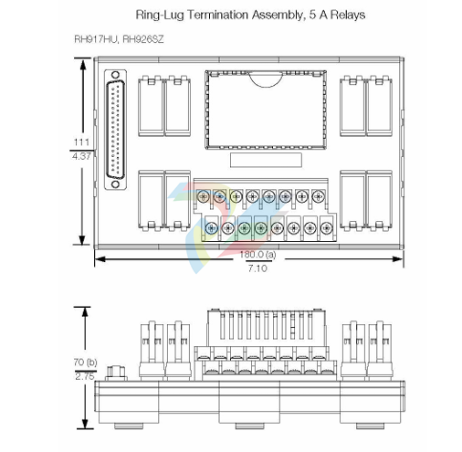
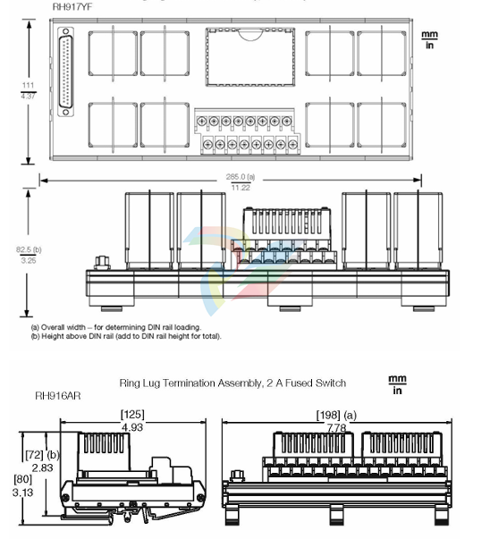
Termination Assemblies
Field I/O signals connect to the FBM subsystem via DIN rail mounted termination
assemblies (TAs). The TAs used with the Compact FBM240 provide:
• Outputsignal connection points
• External power connection point
• 5Aunsealedrelay or a 10 Aunsealed relay for each output
• 15-60VDCswitch andvoltage monitor inputs
The relay TAs have a high voltage input circuit that monitors the voltage across the
contacts of each output relay. Monitor circuits are located on daughter card
assemblies mounted on the TAs. There are two daughter cards per TA, each with four
monitor circuits. The TAs are:
• RH917YF-80to125VDCat5Aor80to120VACat10A
• RH917HU-80to120VACat5A
• RH926SZ-15to30VDCat5A
• RH916AQ/RH916AR-15to60VDCvoltagemonitor and 2 Aswitch
NOTE: WhentheCompact FBM240output opens, the TA contacts still apply
current to the circuit due to the TA’s readback circuitry, as described in Table 2 and
Table 3.
The RH916AQ/ARpassive TA provides fused 2 A outputs and independent inputs for
use with 15-60 VDC.
The redundant adapter connects the redundant FBM’s baseplate connectors together.
The redundant adapter provides a single termination connection to a single TA.
The DIN rail mounted termination assemblies connect to the redundant adapter by
means of a removable termination cable. The cable is available in a variety of lengths,
up to 30 meters (98 feet), allowing the termination assemblies to be mounted as
needed by plant design.
Visual Indicators
Red andgreen light-emitting diodes (LEDs) incorporated into the front of the modules
provide visual status indications of FBM functions, as well as the discrete states of the
individual output points.
-
AMAT 0100-00046 AC Current Sense PWB
-
AMAT A0414720 Precision Advanced System Controller
-
AMAT 0010-00017 Precision Semiconductor Process Interface
-
AMAT 01-82889-00 High-Performance Semiconductor Component
-
ABB Sample Gas Cooler SCC-C 23070-0-10232110
-
IBA ibaRackline-PCHD Efficient process analysis with ibaHD-Server
-
IBA ibaRackline-PC CAM Frame-accurate video information with ibaCapture
-
IBA ibaRackline-PC Highly available and reliable
-
IBA Optical Signal Multiplier ibaBM-FOX-i-3o-D
-
IBA Optical Data Distribution System ibaBM-DIS-i-8o
-
IBA Optical Data Concentrator ibaBM-COL-8i-o
-
IBA ibaNet750-BM-D Acquisition via FO
-
IBA ibaW-750 Acquisition via Ethernet
-
IBA ibaPADU-8AI-I Compact Measurement Modules
-
IBA ibaPADU-D-8AI-I Compact Measurement Modules
-
IBA ibaPADU-D-8AI-U Compact Measurement Modules
-
IBA ibaPADU-4-AI-U Compact Measurement Modules
-
IBA ibaPADU-C-8AI Self-Supplied Data Logger
-
IBA ibaBM-ENetIP Bus monitor for EtherNet/IP
-
IBA ibaBM-eCAT Bus monitor for EtherCAT
-
IBA ibaBM-DP Bus monitor for PROFIBUS
-
IBA ibaBM-PN Bus monitor for PROFINET IO
-
IBA ibaMS3xAI-1A Precision AC Current Measurement Module
-
IBA ibaDAQ Intelligent Central Unit
-
IBA ibaPQU-S Power Quality Monitoring System
-
IBA ibaCMU-S Condition Monitoring Unit (CMU)
-
IBA ibaPADU-S-IT-2x16 Modular data acquisition and control system
-
IBA ibaPADU-S-CM Modular data acquisition system
-
IBA ibaM-4AI-IEPE Input module
-
IBA ibaM-4AI-UI Input module
-
IBA ibaM-4AI-150V-AC Input module
-
IBA ibaM-4AI-600V-AC Input module
-
IBA ibaLink-SM-256V High-Density PLC Data Interface
-
IBA ibaLink-SM-64V High-Performance S5/S7 Interface
-
IBA ibaLink-SM-128V-i-2o Synchronous Fiber Optic (ibaNet)
-
IBA ibaLink-SM-128V communication module
-
IBA ibaM-4AI-5A-150A-AC Input module
-
IBA ibaM-FO-2IO Interface module
-
IBA ibaM-COM Communication module
-
IBA ibaM-DAQ Intelligent Processor Module
-
B&R ECNT43-0 MULTI power supply module
-
B&R ECEP128-0 MULTI application memory
-
B&R ECCP60-01 MULTI CPU type B 42 KByte SRAM
-
B&R DI426 digital input module
-
B&R 2DS100.60-1 electronic drum sequencer Absolut encoder
-
B&R 2CP100.60-1 CPU MODULE
-
B&R 2BM100.9 High-performance I/O module
-
AMAT 0190-14928 SCR Power Controller (PVD Reverse Zone)
-
AMAT 0500-01065 300mm Loadlock Interface Interlock Board
-
AMAT 2000-21123 Advanced Vacuum Seal Assembly
-
AMAT 0660-00090 High-Performance Industrial Power Filter
-
AMAT 0240-34077 Centura Endpoint Controller Kit
-
AMAT 0195-10215 High-Precision Pedestal Assembly
-
AMAT 0190-76050 VGA Video Controller VME Module
-
AMAT 0190-75084 High-Performance Communication & Logic Controller
-
AMAT 0190-60287 Precision VME/cPCI Interface Control Module
-
AMAT 0190-53752 DI Water I/O Controller PCB
-
AMAT 0190-37993 DeviceNet Scanner Pro (3U CompactPCI)
-
AMAT 0190-37833 MKS CDN500R-5 EPI 300mm Interface Module
-
AMAT 0190-37771 MKS CDN500R Interlock Control Module
-
AMAT 0190-37616 High-Precision Analog Input/Output Interface
-
AMAT 0190-36787B ISAC CP I/O Block 2 (Top) - Revision B
-
AMAT 0190-36787 ISAC CP I/O Block 2 (Top)
-
AMAT 0190-36511 DIP294 DeviceNet I/O Control Block
-
AMAT 0190-35764 & 0190-35765: Precision Control Interface Duo
-
AMAT 0190-35763 High-Performance Integrated Power Module
-
Applied Materials (AMAT) 0190-34512: 4-Channel DeviceNet Scanner Interface
-
Applied Materials (AMAT) 0190-34282 High-Stability Process Control Module
-
Applied Materials (AMAT) 0190-27707 High-Precision DeviceNet I/O Controller
-
Applied Materials (AMAT) 0190-27072 High-Performance Semiconductor Interface
-
AMAT 0190-24007 CPCI-3720CF Single Board Computer
-
AMAT 0190-23905 Spellman ESC High Voltage Power Supply
-
AMAT 0190-22967 High-Density Analog I/O Control Board
-
AMAT 0190-22543 High-Precision Analog Input/Output Module
-
AMAT 0190-17894 Interlock Module Conductor HART
-
AMAT 0190-17081 2U CompactPCI System Host Processor
-
AMAT 0190-16926 and 0190-16928 Based on Compact PCI
-
AMAT 0190-15915 Intelligent I/O Control Module
-
AMAT 0190-15840 4-Port UPA DeviceNet Interface Module
-
AMAT 0190-15384 Advanced Digital Signal Interface Module
-
AMAT 0190-15384 Advanced Digital Signal Interface Module
-
AMAT 0190-14027 Wafer Flat Finder PCB
-
AMAT 0190-12695 SBS CL7 3U CompactPCI Single Board Computer
-
AMAT 0190-11817 CP3-SER16-TTL 16-Port Serial Interface Card
-
AMAT 0190-11524 CDN500-25 Interlock Module
-
AMAT 0190-07450 CompactPCI 48-Channel Digital I/O Interface Board
-
AMAT 0190-05990-001 Maglev Rotation System Controller (300mm)
-
AMAT 0190-05647 LK3710 Serial Module Transition Card
-
AMAT 0190-04457 High-Performance Integrated Circuit Control Module
-
Applied Materials (AMAT) 0190-04098 | 5.X Factory Interface I/O Distribution Board
-
Applied Materials (AMAT) 0190-03705 | MF Producer SE/E Interlock Module
-
Applied Materials (AMAT) 0190-02748 | Flex Scanner Transition Module
-
Applied Materials (AMAT) 0190-01227 | Intelligent Motor Control OMS Board
-
Applied Materials (AMAT) 0190-00318 | VME 486 Video Controller
-
Applied Materials (AMAT) 0130-14007 | Advanced RF Signal Assembly
-
Applied Materials (AMAT) 0130-14005 | RF Cable/Interface Assembly
-
Applied Materials (AMAT) 0110-77040 | Head Pneumatic Controller
-
Applied Materials (AMAT) 0110-00077 | Precision Control Module
-
AMAT 0101-57015 high-performance Next-Generation Deflection Amplifier Board
-
AMAT 0100-77040 critical Head Pneumatic Controller Board
-
AMAT 0100-76291 Data Buffer / Memory Expansion Interface
-
AMAT 0100-76290 Advanced I/O Interface Board
-
AMAT 0100-76269 Control Board / Interface Module
-
AMAT 0100-71462-01 high-performance Process Controller PCB
-
AMAT 0100-71171 Chamber Interlock Control PCB
-
AMAT 0100-71154 Semiconductor Circuit Board / Electronic Group Card
-
AMAT 0100-70034 PCB Assembly (PCBA) for Endpoint VGA I/O Interconnect.
-
AMAT 0100-38032 ESC (Electrostatic Chuck) Controller PCB
-
AMAT 0100-36035 DPS Source Match / Seriplex I/O Distribution PCB
-
AMAT 0100-35231 Seriplex I/O Distribution Module
-
AMAT 0100-35217 TC Amp Interlock PCB Module
-
AMAT 0100-35065 High-Precision Serial Isolator PCB
-
AMAT 0100-35054 Advanced Chamber Interface Module
-
AMAT 0100-20453 DeviceNet Digital I/O Interface Board
-
AMAT 0100-20100 High-Performance Semiconductor Component
-
AMAT 0100-20068 Precision CCD Image Control Board
-
AMAT 0100-20064 Advanced Semiconductor Control Module
-
AMAT 0100-20018 Advanced Communication Interface Module
-
Applied Materials (AMAT) 0100-20016 High-Performance Interface and Control Module
-
Applied Materials (AMAT) 0100-20003 Digital I/O (DI/DO) Interface Board
-
Applied Materials (AMAT) 0100-20001 System Electronics Interface (SEI) / PCB Assembly
-
Applied Materials (AMAT) 0100-11030 Chamber Hardware / Gas Distribution Component
-
Applied Materials (AMAT) 0100-11022 Semiconductor Board Card
-
Applied Materials (AMAT) 0100-11018 Advanced Interface Control Module
-
Applied Materials (AMAT) 0100-11001 Precision Analog Output Board
-
Applied Materials (AMAT) 0100-11000 High-Precision Analog Input Board
-
Applied Materials (AMAT) 0100-09237 Advanced Signal Interface Module
-
Applied Materials (AMAT) 0100-09204 Advanced Digital Interface Control Board
Add: High-tech Software Park, Xiamen City, Fujian Province
Mobile: +86-17750019513(WhatsApp)
Email: yy4291644@gmail.com
Website: https://www.abb-sis.com
.jpg)
.jpg)
.jpg)
.jpg)
.jpg)
.jpg)

-
AMAT 0100-00046 AC Current Sense PWB
-
AMAT A0414720 Precision Advanced System Controller
-
AMAT 0010-00017 Precision Semiconductor Process Interface
-
AMAT 01-82889-00 High-Performance Semiconductor Component
-
ABB Sample Gas Cooler SCC-C 23070-0-10232110
