

Melcher W Series 125, 250 Watt AC-DC and DC-DC DIN-Rail Converters Convert Select LWN2660-6E-G
The secondary side of the main transformer supplies via the rectifier diode a large electrolytic output storage capacitor providing for the hold-up time. Double-output models exhibit an individual control logic each. The output voltage and the output current are measured and fed back to the primary control logic via an optocoupler. A second control loop monitors the output voltage. It disables the output in the case of a failure in the control logic and limits the output voltage. Built-in temperature sensors monitor the internal temperature of each powertrain. If the temperature exceeds the limit, the converter reduces the output power continuously to keep the temperature below its limit. A green LED on the front cover confirms the presence of the output voltage(s).
The R input (option R, M1, or M2) allows for external adjustment of the output voltage by means of a resistor or an external voltage source. An external sensor can be connected to the R input and allows for temperature-controlled battery charging (see Accessories).
Output Power Derating
The output power of LW models must be decreased at low input voltage and/or powertrain temperature above 125 °C.
The powertrain temperature depends on the output power, the input voltage, and the cooling method. At low input voltage the losses increase. At the maximum specified environment temperature TA free air convection cooling might be insufficient approaching maximum ambient conditions. As a result, the output power has to be reduced according to the tables below.
Note: The measurements have been made by the approval boards with free air convection cooling according to 62368-1 3rd edition specified ambient temperature TA and with the converter built in a cardboard box according to UL 508 and a specified temperature outside the box Tout .
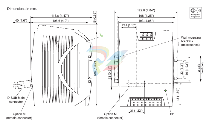
The tables give a correlation between TA or Tout and the case temperature TC (measuring point TC see Mechanical Data). For models not specified, please contact the Company
EW models need no derating.
Input Fuse and Protection
A fast-blow fuse (Schurter F 6.3A, 5 × 20 mm), protected by a sleeve, is connected to the input L [W/V]-0.67-1.25-0.67-1.25 or Vi+. EW models have a smaller fuse (250 V, 4 × 9 mm, SOC NT3 6.3A V009, UL-recognized E-39265). For DC input voltages above 250 V consult the Installation Instructions.
Converters with option F have large fuses (F6.3A, 5 × 20 mm). The DC input voltage for converters with option F is limited to 250 V. A VDR and a symmetrical input filter form an effective protection against input transients.
An under- and an overvoltage lockout protect the converter, which is disabled below Vi min and above Vi max by an internally generated inhibit signal.
The built-in bridge rectifier (LW models) provides reverse polarity protection at the input if operated from DC. EW models are protected by the (blowing) input fuse in connection with the body diode of the main transistor. Option Q offers a serial diode, but this reduces the efficiency by approx. 1%.
Parallel Operation
Double-output models exhibit an independent control logic each. Both outputs can be con nected in parallel, provided that options S (included in M1) and R are not used, since they influence only the 2nd output. The two power trains share the current due to their output voltage droop characteristic.
Up to 3 converters with the same output voltage may be operated in parallel. It is possible to parallel W Series with X Series converters.
Reasonable current sharing is achieved by the droop characteristic. Correct mode of operation is highly dependent upon the wiring of the converters and the impedance of these wires. Use wires with equal length and equal cross sections of min. 1.5 mm2. The best results for parallel operation can be achieved with the wiring shown in fig. 6.
Parallel operation of single-output models using the option R (output voltage adjust) is possible, but not recommended. Refer to f ig. 6; the connections between the pins 8 and 9 (both Vo–) should be as short as possible.
Note: Parallel operation is not possible, if a temperature sensor is connected, as the sensor eliminates the output voltage droop.
Note: For ORing diodes, we recommend to use Schottky diodes, mounted on a common heatsink to avoid thermal run away (or the use of double diodes).
Output Characteristic and Protection
The output characteristic, individual for each powertrain, is rectangular with a droop to ease parallel operation; see fig. 7. However, a 50% higher output current is possible for a short time, such allowing start-up of loads or charging of capacitors; see fig. 8. Each output is independently protected against internal overvoltage by means of a second control loop. When the output voltage exceeds Vo L , the respective output is disabled.
Overtemperature Protection 1.4 1.6 1.2 1.0 0.8 0.6-- 0.5 0.5 1.5 2.5 s Io / Io nom 05194b 0 1 2 Fig. 8 Short term peak power characteristic: overcurrent versus time (typical values). A built-in temperature sensor protects each powertrain is independently protected against over temperature. When a certain temperature is reached, the concerned powertrain reduces its output power continuously. Thermal Considerations The thermal conditions are influenced by input voltage, output current, airflow, and temperature of surrounding components. TA max is therefore, contrary to TC max , an indicative value only. Caution: The installer must ensure that under all operating conditions TC remains within the limits stated in the table Temperature specifications. Note: Sufficient forced cooling allows TA to be higher than TA max provided that TC max is not exceeded. It is recommended that continuous operation under worst case conditions of the following 3 parameters be avoided: Minimum input voltage, maximum output power, and maximum temperature. Battery Charging and Temperature Sensor The battery charger models exhibit the option M1 and have been designed to charge lead-acid batteries. The R-input allows for connecting a battery-specific temperature sensor, which provides temperature controlled adjust of the trickle charge voltage. This optimizes charging as well as battery life time. Depending upon the cell voltage and the temperature coefficient of the battery, different sensor types are available; see Accessories. Note: Parallel operation is not possible, if the temperature sensor is connected to the paralleled outputs Vo+, as the sensor eliminates the output voltage droop. However, it is possible to insert bleeding resistors in the Vo+ output lines of each converter in order to create a droop of approx. 0.6 V @ Io nom for 24 V outputs (1.2 V @ Io nom for 48V outputs), but this creates considerable power losses.
-
ADLINK Multi-Function DAQ PCI-9222/9223
-
ADLINK PICMG Single Board Computers NuPRO-A40H
-
ADLINK HSL-4XMO HSL-4XMO-TB-D103 HSL-4XMO-CD-N-006
-
ADLINK industrial computer motherboard NuPRO-965DV
-
ADLINK PCI-7442 switch card Digital I/O
-
ADLINK PCI-7260 Digital I/O
-
ADLINK PICMG Single Board Computers NuPRO-852
-
ADlink 6U CompactPCI 2.0 Blades cPCI-6840
-
Adlink PICMG Single Board Computers NuPRO-935A
-
ADLINK ADLINK NuPRO-841 REV:1.0 PICMG Single Board Computers
-
ADLINK PCI-8254 / PCI-8258 DSP-based 4/8-axis Advanced Motion Controllers
-
ADLINK NUPRO-780 PICMG Single Board Computers
-
ADLINK USB-7230/7250 Isolated USB Digital I/O Modules
-
ADLINK USB-7230/7250 Isolated USB Digital I/O Modules
-
Adlink Technology 51-37111-0C1 cPCI-R8217 cPCI-R3700A PCB Interface Card
-
ADLINK DPAC-3020-11(G) Embedded PC Automation Controller
-
ADLINK NuPRO-840 PICMG 1.0 industrial Single Board
-
Adlink 6U CompactPCI 2.0 Blades cPCI-6965
-
ADLINK PCI-9114DG Multi-Function DAQ Card
-
Adlink NuPRO-E43 PICMG Single Board Computers
-
Adlink PCI-7856 Distributed Motion Control
-
ADLINK Mini-ITX Embedded Boards MI-965
-
ADLINK NuPRO-E340 ICMG Single Board Computers
-
ADLINK NuPRO-595 Series Full-Size PICMG 1.0 SBC
-
ADLINK PCIe-GIE64+ / PCIe-GIE62+ 4 / 2-CH PCI Express® Power over Ethernet Frame Grabbers
-
ADLINK CPCI-6910AM-M1G 6U Dual Core Xeon CompactPCI Universal SBC
-
ADLINK/AMPRO CM-435-v2/CM-435 Extreme Rugged™ PC/104 Single Board Computer
-
ADLINK Technology 51-37111-0C1 PCB Interface Card
-
Adlink Centralized Motion Controllers PCI-8164
-
ADLINK PCI-7230/33/34 32-CH Isolated DIO PCI Cardsrd
-
ADLINK NUPRO-E320DV industrial control motherboard
-
Adlink PCI-8154 Advanced 4-axis Servo & Stepper Motion Controller
-
Adlink cPCI-3534/3538-S Series 4/8-port Asynchronous Serial Communications Modules
-
ADLINK Adlink Digital I/O PCI-7396
-
ADLINK 6U Rear Transition Modules cPCI-R6700 Series
-
ADLINK cPCI-6700B Industrial Control Board
-
ADLINK NuPRO-965/ NuPRO-965LV PICMG Single Board Computers
-
ADLINK HSL-DI16DO16-M-NN 16-CH Discrete Input 16-CH Discrete Output Module
-
Adlink cPCI-6770 6U CompactPCI 2.0 Blades
-
ADLINK NuPRO-598 REV A1 INDUSTRIAL CONTROL MOTHERBOARD
-
ADLINK PCI-7200 PCI Motion Control Card Acquisition Card 51-12001-0C20
-
ADLINK TECHNOLOGY EOS-1200/M4G/SSD32G(G) Industrial Systems
-
ADLINK Centralized Motion Controllers PCI-8134
-
ADLINK cPCI-HR6847E/M2G-1 COMPACT PCI BOARD
-
ADLINK PXIE-8638 BUS EXPANSION MODULE
-
ADLINK cPCI-6910 6U CompactPCI 2.0 Blades
-
Adlink NuPRO-E42 51-41808-0A30 Industrial Motherboard
-
ADLINK IH61-AA400-A4A1E (IMB-M40H) Industrial Motherboard
-
ADLINK PCIe-GIE64+ GigE Vision Frame Grabber Card
-
ADLINK MXC-6322D(G) Industrial Fanless Computer working
-
ADLINK CPCI-7300 32-CH 80 MB/s High-Speed Digital I/O Module
-
Adlink cPCI-8168 Advanced 6U Compact PCI 8-Axis Motion Controller
-
Adlink VME CPU Board cPCI-6626/2710/M4G
-
ADLINK cPCI-R6200 high-performance 6U CompactPCI Rear Transition Module (RTM)
-
Adlink cPCI-7248 48-CH Opto-22 Compatible Digital I/O Module
-
ADLINK DLAP-211-JNX/DLAP-211-JT2/ DLAP-211-Nan
-
ADLINK cPCI-3544 4-Port RS-422/485 Isolated Serial Communications Card
-
Hirschmann MSP30-16040SCZ999HHE2A Manage the basic unit of the industrial DIN-Rail switch
-
Hirschmann MSP30-16040SCY999HHE2A
-
Hirschmann RS20-0400S2S2SDAEHC09.0.00 Management-type industrial fast Ethernet switch
-
Hirschmann Belden OCTOPUS OS20-002800T5T5T5-TBBY999GMSE3S Manageable industrial Ethernet switch
-
HIRSCHMANN OS20-000800T5T5T5-TBBU999H5SE2S
-
HIRSCHMANN RS20-0800M4M4SDAEHC09.0.14 industrial switch
-
Hirschmann RS20-0800T1T1SDAUHC RS20-0800T1T1SDAE
-
Hirschmann MSM20-M2M2M2M2SY9HH9E99.9 Fast Ethernet Media Module
-
HIRSCHMANN MAR1040-4C4C4C4C9999SMMHPHH Managed Etherne
-
HIRSCHMANN MAR1040-4C4C4C4C9999SMMHPHH Managed Etherne
-
HIRSCHMANN MAR1040-4C4C4C4C9999SM9HRHH Managed Etherne
-
HIRSCHMANN MAR1040-4C4C4C4C9999SM9HPHH05.1.00 industrial switch
-
HIRSCHMANN MM20-P9P9M2T1SAHH Fast Ethernet media module
-
HIRSCHMANN MM20-P9T1T1T1SAHH hot-swappable hybrid media module
-
HIRSCHMANN MM20-Z6Z6T1M2SAHH Fast Ethernet media module
-
HIRSCHMANN MM20-Z6M2M2T1SAHH Fast Ethernet media module
-
HIRSCHMANN MM20-Z6Z6Z6T1SAHH media module.
-
HIRSCHMANN MM20-Z6T1T1T1EBH Fast Ethernet media card.
-
Hirschmann MM20-Z6T1T1T1SAHH Hot-swappable fast Ethernet media module
-
Hirschmann MM20-Z6Z6M2M2EBH media module
-
HIRSCHMANN MM20-Z6Z6T1T1SZHH Technical Datasheet & SEO Guide
-
HIRSCHMANN MM20-Z6Z6T1T1EBH Technical Datasheet & Overview
-
HIRSCHMANN MM20-Z6Z6Z6Z6SZHH Media Module
-
HIRSCHMANN MM20-M4M2M2T1SAHH Media Module
-
HIRSCHMANN MM20-M4T1M2T1SAHH Media Module
-
HIRSCHMANN MM20-M2M2T1T1EBH Media Module
-
HIRSCHMANN MM20-M2M2T1T1SAHH Media Module
-
HIRSCHMANN MM20-M2T1T1T1TAHH Media Module
-
HIRSCHMANN MM20-M2T1T1T1EBH Media Module
-
HIRSCHMANN MM20-M2T1T1T1SAHH Media Module
-
HIRSCHMANN MM20-M2T1T1T1SAHH Media Module
-
HIRSCHMANN MM20-M2T1T1T1SAHH Media Module
-
HIRSCHMANN MM20-M2T1T1T1SAHH Media Module
-
HIRSCHMANN MM20-M2M2M2M2EBH Industrial Ethernet Media Module
-
HIRSCHMANN RS20-1600S2S2SDAEHH09.0.14 Ethernet switch
-
HIRSCHMANN MSM20-M2M2T1T1SY9HH9E99.9.99
-
HIRSCHMANN MSM20-M2M2M2M2SY9HH9E Ethernet media modul
-
HIRSCHMANN SPIDER-PL-20-05T1999999TWVHHHH Industrial Ethernet Rail Switch
-
Hirschmann SPIDER-PL-20-07T1M2M299TWVHHHH Industrial ETHERNET Rail Switch
-
Hirschmann (Belden) RS20-1600M2M2SDAEHC09.1.00 DIN-rail managed industrial Fast Ethernet switch
-
Hirschmann (Belden) RS30-1602O6O6TDAPHC09.1.00 DIN-rail managed industrial Ethernet switch
-
Hirschmann RS30-2402O6O6SDAP Ethernet switch
-
Hirschmann (Belden) RS30-2402O6T1SDAPHH09.0.13 DIN-rail industrial Ethernet switch
-
Hirschmann (Belden) RS30-2402O6T1SDAPHH09.0.13 DIN-rail industrial Ethernet switch
-
Hirschmann (Belden) SPIDER-PL-20-04T1S29999TY9HHHH Ethernet DIN-rail switch
-
HIRSCHMANN RS20-1600T1T1SDAUHX Switch
-
HIRSCHMANN BRS42-0012OOOO-SPCZ99HHSES industrial switch
-
Hirschmann RS20-0800S2S2TDHPHH09.0.14 Fast Ethernet DIN rail switch.
-
HIRSCHMANN MM20-Z6Z6M2M2SAHH Hybrid Fast Ethernet Media Module
-
HIRSCHMANN MM20-Z6Z6T1T1SAHH hot-swappable hybrid Fast Ethernet Media Module
-
HIRSCHMANN MM20-P9P9T1T1SAHH Hybrid Fast Ethernet Media Module
-
HIRSCHMANN MM20-M4T1T1T1SAHH Hybrid Fast Ethernet Media Module
-
HIRSCHMANN MM20-M4M4T1T1SAHH Hybrid Fast Ethernet Media Module
-
HIRSCHMANN MM20-M2M2M2M2SZHH Ethernet media module
-
HIRSCHMANN MM20-M2M2M2M2SAHH Ethernet media module
-
HIRSCHMANN MM20-T1T1T1T1EBH 4-port Fast Ethernet Copper Cable Media Module
-
HIRSCHMANN MM20-T1T1T1T1SAHH 4-port Fast Ethernet Copper Cable Media Module
-
HIRSCHMANN MM20-Z6Z6EBH Hot-swappable fast Ethernet media module
-
HIRSCHMANN MM20-Z6Z6SAHH Ethernet media module
-
HIRSCHMANN MM20-Z6Z6Z6Z6EBH Industrial Media Module
-
MSM40-T1T1T1TZ9HH9E99.9.99 HIRSCHMANN Switch
-
HIRSCHMANN MS20-0800SAAEHC / MS20-0800SAAEHC0 8-port modular Layer 2 management Ethernet switch
-
Hirschmann RSPM20-4T14T1SZ9HHS9 Switch RSPM20-4T14T1SZ9HHS9
-
HIRSCHMANN RS20-1600M2M2SDAEHH09.1. RS20/30/40 Managed Switch configurator
-
HIRSCHMANN RS20-1600M2M2SDAEHX09.0.00 Ethernet switch
-
HIRSCHMANN BELDEN SPIDER-PL-20-07T1M2M299TY9HHHH / SPIDERPL2007T1M2M299TY9HHHH
-
HIRSCHMANN MM3-1FXS2/3TX1 Switching Board Module
-
HIRSCHMANN RSPE30-24044O7T99-SCCV999HHSI2SXX.X.XX Switch
-
HIRSCHMANN RSPE30-24044O7T99-ECCP999HHSE2A08.1.00 Industrial-grade fanless management-type Ethernet switch
-
HIRSCHMANN RS30-1602OOZZSDAEHC09.1.00 DIN-rail-mounted managed Layer 2 Ethernet switch
-
HIRSCHMANN MACH104-20TX-F Managed 24-port Full Gigabit 19" Switch
Add: High-tech Software Park, Xiamen City, Fujian Province
Mobile: +86-17750019513(WhatsApp)
Email: yy4291644@gmail.com
Website: https://www.abb-sis.com
.jpg)
.jpg)
.jpg)
.jpg)
.jpg)
.jpg)

-
ADLINK Multi-Function DAQ PCI-9222/9223
-
ADLINK PICMG Single Board Computers NuPRO-A40H
-
ADLINK HSL-4XMO HSL-4XMO-TB-D103 HSL-4XMO-CD-N-006
-
ADLINK industrial computer motherboard NuPRO-965DV
-
ADLINK PCI-7442 switch card Digital I/O
