

Melcher W Series 125, 250 Watt AC-DC and DC-DC DIN-Rail Converters Convert Select LWN2660-6E-G
Installation Instructions
The converters of the W Series are components, intended exclusively for inclusion within other equipment by professional installers. Installation must strictly follow the national safety regulations in compliance with the enclosure, mounting, creepage, clearance, casualty, markings and segregation requirements of the end-use application.
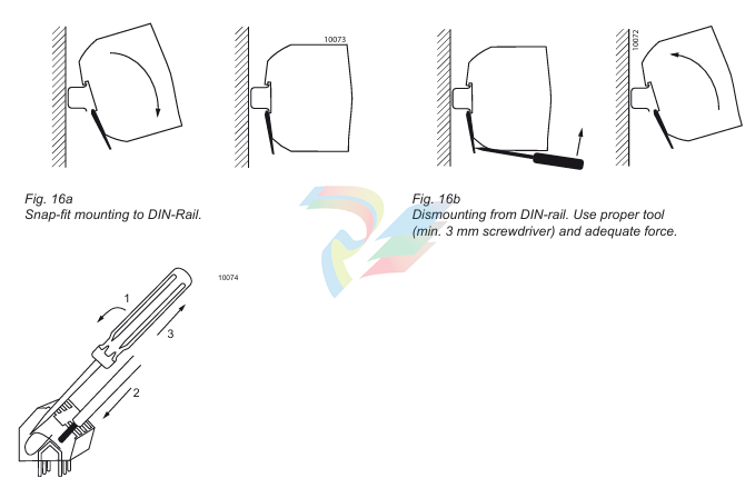
DIN-rail mounting is possible with the built-in snap-fit device on a DIN-rail. This fulfills the mechanical transport re quirements as per ETSI 300019-1-2, class 2 (vertical). To fulfill the requirements of IEC 721-3-2, class 2.1 (vertical), 2 additional fixing brackets HZZ00624-G (see Accessories) must be fitted on the bottom side of the DIN-rail. For heavy duty railway applications, we recommend installing all 4 fixing brackets HZZ00624-G.
Chassis or wall mounting is possible using the universal chassis-mounting brackets HZZ00618-G (see Accessories). Such installa tion complies with IEC 721-3-2, class 2.2 (vertical and horizontal).
Caution: Install the converters vertically, and make sure that there is sufficient airflow available for convection cooling. The minimum space to the next device should be: top/bottom: 30 mm, left/right: 20 mm.
The converters of the W Series are class I equipment: Input terminal 1 ( ) and the output terminals 1 and 11 ( connected to the case. For safety reasons it is essential to connect the input terminal 1 ( ) are reliably ) with protective earth. Output terminals 1 and 11 can be used to connect the output voltage(s) or the load to functional earth.
The phase input (L or Vi+) is internally fused; see Input Fuse. This fuse is de signed to break an overcurrent in case of a malfunction of the converter and is not customer-accessible. External fuses in the wiring to one or both input lines (L and/or N ) may be necessary to ensure compliance with local requirements. A built-in second fuse in the neutral path is available as option F. A second fuse in the wiring to the neutral terminal N or option F is needed if:
• Local requirements demand an individual fuse in each source line
• Neutral and earth impedance is high or undefined
• Phase and neutral of the mains are not defined or cannot be assigned to the corresponding terminals (L Models with Option F: Caution! Double-pole/neutral fusing. to phase and N to neutral). If the converters operate at source voltages above 250 VDC, an external fuse or a circuit breaker at system level should be installed. Caution:
• Installation must strictly follow the national safety regulations.
• Do not open this apparatus
Standards and Approvals The converters of the LW Series with feature E were safety-approved to IEC/EN 62368-1 3rd edition and UL/CSA 60950-1 2nd edition (models without E: IEC/EN 62368-1 3rd edition), IEC 61010-1:C11:2002 (models without E: IEC 61010-1), and EN 50178:1997 (with and without E). The converters are UL508-listed components. The EW models are safety-approved to IEC/EN 62368-1 3rd edition and UL/CSA 60950-1 2nd edition The converters have been designed in accordance with said standards for:
• Class I equipment
• Power supply for building-in, vertical mounting on 35 mm DIN-rail or on a wall
• Overvoltage category II (III for 110 VAC supply)
• Basic insulation between input and case, based on 250 VAC
• Double or reinforced insulation between input and output, based on 250 VAC and 350 VDC.
• Functional insulation between outputs and case.
• Functional insulation between outputs.
• Pollution degree 2 environment. The converters are subject to manufacturing surveillance in accordance with the above mentioned standards and with ISO9001:2015. Operation at Frequencies Greater 60 Hz The LW Series converters have been tested for operation up to 440 Hz. However, the Y and X caps are not approved to such frequency. The leakage currents are higher than at 60 Hz, whereas the output ripple voltage is lower. Leakage Currents with AC Supply Leakage currents flow due to internal leakage capacitance and RFI suppression Y-capacitors. The current values are proportional to the mains voltage and nearly proportional to the mains frequency. They are specified at maximum operating input voltage where phase, neutral, and protective earth are correctly connected as required for class I equipment. Leakage current may exceed 5 mA, if f i > 63 Hz. Railway Applications The W Series converters have been designed observing the railway standards EN 50155 and EN 50121. All boards are coated with a protective lacquer. The EW Series is particularly suitable for connection to 110 V railway batteries. Isolation The electric strength test is performed in the factory as routine test in accordance with EN 62911 and IEC/EN 62368-1 3rd edition and should not be repeated in the field. The Company will not honor warranty claims resulting from incorrectly executed electric strength field tests.
Safety of Operator-Accessible Output Circuits
-
ADLINK Multi-Function DAQ PCI-9222/9223
-
ADLINK PICMG Single Board Computers NuPRO-A40H
-
ADLINK HSL-4XMO HSL-4XMO-TB-D103 HSL-4XMO-CD-N-006
-
ADLINK industrial computer motherboard NuPRO-965DV
-
ADLINK PCI-7442 switch card Digital I/O
-
ADLINK PCI-7260 Digital I/O
-
ADLINK PICMG Single Board Computers NuPRO-852
-
ADlink 6U CompactPCI 2.0 Blades cPCI-6840
-
Adlink PICMG Single Board Computers NuPRO-935A
-
ADLINK ADLINK NuPRO-841 REV:1.0 PICMG Single Board Computers
-
ADLINK PCI-8254 / PCI-8258 DSP-based 4/8-axis Advanced Motion Controllers
-
ADLINK NUPRO-780 PICMG Single Board Computers
-
ADLINK USB-7230/7250 Isolated USB Digital I/O Modules
-
ADLINK USB-7230/7250 Isolated USB Digital I/O Modules
-
Adlink Technology 51-37111-0C1 cPCI-R8217 cPCI-R3700A PCB Interface Card
-
ADLINK DPAC-3020-11(G) Embedded PC Automation Controller
-
ADLINK NuPRO-840 PICMG 1.0 industrial Single Board
-
Adlink 6U CompactPCI 2.0 Blades cPCI-6965
-
ADLINK PCI-9114DG Multi-Function DAQ Card
-
Adlink NuPRO-E43 PICMG Single Board Computers
-
Adlink PCI-7856 Distributed Motion Control
-
ADLINK Mini-ITX Embedded Boards MI-965
-
ADLINK NuPRO-E340 ICMG Single Board Computers
-
ADLINK NuPRO-595 Series Full-Size PICMG 1.0 SBC
-
ADLINK PCIe-GIE64+ / PCIe-GIE62+ 4 / 2-CH PCI Express® Power over Ethernet Frame Grabbers
-
ADLINK CPCI-6910AM-M1G 6U Dual Core Xeon CompactPCI Universal SBC
-
ADLINK/AMPRO CM-435-v2/CM-435 Extreme Rugged™ PC/104 Single Board Computer
-
ADLINK Technology 51-37111-0C1 PCB Interface Card
-
Adlink Centralized Motion Controllers PCI-8164
-
ADLINK PCI-7230/33/34 32-CH Isolated DIO PCI Cardsrd
-
ADLINK NUPRO-E320DV industrial control motherboard
-
Adlink PCI-8154 Advanced 4-axis Servo & Stepper Motion Controller
-
Adlink cPCI-3534/3538-S Series 4/8-port Asynchronous Serial Communications Modules
-
ADLINK Adlink Digital I/O PCI-7396
-
ADLINK 6U Rear Transition Modules cPCI-R6700 Series
-
ADLINK cPCI-6700B Industrial Control Board
-
ADLINK NuPRO-965/ NuPRO-965LV PICMG Single Board Computers
-
ADLINK HSL-DI16DO16-M-NN 16-CH Discrete Input 16-CH Discrete Output Module
-
Adlink cPCI-6770 6U CompactPCI 2.0 Blades
-
ADLINK NuPRO-598 REV A1 INDUSTRIAL CONTROL MOTHERBOARD
-
ADLINK PCI-7200 PCI Motion Control Card Acquisition Card 51-12001-0C20
-
ADLINK TECHNOLOGY EOS-1200/M4G/SSD32G(G) Industrial Systems
-
ADLINK Centralized Motion Controllers PCI-8134
-
ADLINK cPCI-HR6847E/M2G-1 COMPACT PCI BOARD
-
ADLINK PXIE-8638 BUS EXPANSION MODULE
-
ADLINK cPCI-6910 6U CompactPCI 2.0 Blades
-
Adlink NuPRO-E42 51-41808-0A30 Industrial Motherboard
-
ADLINK IH61-AA400-A4A1E (IMB-M40H) Industrial Motherboard
-
ADLINK PCIe-GIE64+ GigE Vision Frame Grabber Card
-
ADLINK MXC-6322D(G) Industrial Fanless Computer working
-
ADLINK CPCI-7300 32-CH 80 MB/s High-Speed Digital I/O Module
-
Adlink cPCI-8168 Advanced 6U Compact PCI 8-Axis Motion Controller
-
Adlink VME CPU Board cPCI-6626/2710/M4G
-
ADLINK cPCI-R6200 high-performance 6U CompactPCI Rear Transition Module (RTM)
-
Adlink cPCI-7248 48-CH Opto-22 Compatible Digital I/O Module
-
ADLINK DLAP-211-JNX/DLAP-211-JT2/ DLAP-211-Nan
-
ADLINK cPCI-3544 4-Port RS-422/485 Isolated Serial Communications Card
-
Hirschmann MSP30-16040SCZ999HHE2A Manage the basic unit of the industrial DIN-Rail switch
-
Hirschmann MSP30-16040SCY999HHE2A
-
Hirschmann RS20-0400S2S2SDAEHC09.0.00 Management-type industrial fast Ethernet switch
-
Hirschmann Belden OCTOPUS OS20-002800T5T5T5-TBBY999GMSE3S Manageable industrial Ethernet switch
-
HIRSCHMANN OS20-000800T5T5T5-TBBU999H5SE2S
-
HIRSCHMANN RS20-0800M4M4SDAEHC09.0.14 industrial switch
-
Hirschmann RS20-0800T1T1SDAUHC RS20-0800T1T1SDAE
-
Hirschmann MSM20-M2M2M2M2SY9HH9E99.9 Fast Ethernet Media Module
-
HIRSCHMANN MAR1040-4C4C4C4C9999SMMHPHH Managed Etherne
-
HIRSCHMANN MAR1040-4C4C4C4C9999SMMHPHH Managed Etherne
-
HIRSCHMANN MAR1040-4C4C4C4C9999SM9HRHH Managed Etherne
-
HIRSCHMANN MAR1040-4C4C4C4C9999SM9HPHH05.1.00 industrial switch
-
HIRSCHMANN MM20-P9P9M2T1SAHH Fast Ethernet media module
-
HIRSCHMANN MM20-P9T1T1T1SAHH hot-swappable hybrid media module
-
HIRSCHMANN MM20-Z6Z6T1M2SAHH Fast Ethernet media module
-
HIRSCHMANN MM20-Z6M2M2T1SAHH Fast Ethernet media module
-
HIRSCHMANN MM20-Z6Z6Z6T1SAHH media module.
-
HIRSCHMANN MM20-Z6T1T1T1EBH Fast Ethernet media card.
-
Hirschmann MM20-Z6T1T1T1SAHH Hot-swappable fast Ethernet media module
-
Hirschmann MM20-Z6Z6M2M2EBH media module
-
HIRSCHMANN MM20-Z6Z6T1T1SZHH Technical Datasheet & SEO Guide
-
HIRSCHMANN MM20-Z6Z6T1T1EBH Technical Datasheet & Overview
-
HIRSCHMANN MM20-Z6Z6Z6Z6SZHH Media Module
-
HIRSCHMANN MM20-M4M2M2T1SAHH Media Module
-
HIRSCHMANN MM20-M4T1M2T1SAHH Media Module
-
HIRSCHMANN MM20-M2M2T1T1EBH Media Module
-
HIRSCHMANN MM20-M2M2T1T1SAHH Media Module
-
HIRSCHMANN MM20-M2T1T1T1TAHH Media Module
-
HIRSCHMANN MM20-M2T1T1T1EBH Media Module
-
HIRSCHMANN MM20-M2T1T1T1SAHH Media Module
-
HIRSCHMANN MM20-M2T1T1T1SAHH Media Module
-
HIRSCHMANN MM20-M2T1T1T1SAHH Media Module
-
HIRSCHMANN MM20-M2T1T1T1SAHH Media Module
-
HIRSCHMANN MM20-M2M2M2M2EBH Industrial Ethernet Media Module
-
HIRSCHMANN RS20-1600S2S2SDAEHH09.0.14 Ethernet switch
-
HIRSCHMANN MSM20-M2M2T1T1SY9HH9E99.9.99
-
HIRSCHMANN MSM20-M2M2M2M2SY9HH9E Ethernet media modul
-
HIRSCHMANN SPIDER-PL-20-05T1999999TWVHHHH Industrial Ethernet Rail Switch
-
Hirschmann SPIDER-PL-20-07T1M2M299TWVHHHH Industrial ETHERNET Rail Switch
-
Hirschmann (Belden) RS20-1600M2M2SDAEHC09.1.00 DIN-rail managed industrial Fast Ethernet switch
-
Hirschmann (Belden) RS30-1602O6O6TDAPHC09.1.00 DIN-rail managed industrial Ethernet switch
-
Hirschmann RS30-2402O6O6SDAP Ethernet switch
-
Hirschmann (Belden) RS30-2402O6T1SDAPHH09.0.13 DIN-rail industrial Ethernet switch
-
Hirschmann (Belden) RS30-2402O6T1SDAPHH09.0.13 DIN-rail industrial Ethernet switch
-
Hirschmann (Belden) SPIDER-PL-20-04T1S29999TY9HHHH Ethernet DIN-rail switch
-
HIRSCHMANN RS20-1600T1T1SDAUHX Switch
-
HIRSCHMANN BRS42-0012OOOO-SPCZ99HHSES industrial switch
-
Hirschmann RS20-0800S2S2TDHPHH09.0.14 Fast Ethernet DIN rail switch.
-
HIRSCHMANN MM20-Z6Z6M2M2SAHH Hybrid Fast Ethernet Media Module
-
HIRSCHMANN MM20-Z6Z6T1T1SAHH hot-swappable hybrid Fast Ethernet Media Module
-
HIRSCHMANN MM20-P9P9T1T1SAHH Hybrid Fast Ethernet Media Module
-
HIRSCHMANN MM20-M4T1T1T1SAHH Hybrid Fast Ethernet Media Module
-
HIRSCHMANN MM20-M4M4T1T1SAHH Hybrid Fast Ethernet Media Module
-
HIRSCHMANN MM20-M2M2M2M2SZHH Ethernet media module
-
HIRSCHMANN MM20-M2M2M2M2SAHH Ethernet media module
-
HIRSCHMANN MM20-T1T1T1T1EBH 4-port Fast Ethernet Copper Cable Media Module
-
HIRSCHMANN MM20-T1T1T1T1SAHH 4-port Fast Ethernet Copper Cable Media Module
-
HIRSCHMANN MM20-Z6Z6EBH Hot-swappable fast Ethernet media module
-
HIRSCHMANN MM20-Z6Z6SAHH Ethernet media module
-
HIRSCHMANN MM20-Z6Z6Z6Z6EBH Industrial Media Module
-
MSM40-T1T1T1TZ9HH9E99.9.99 HIRSCHMANN Switch
-
HIRSCHMANN MS20-0800SAAEHC / MS20-0800SAAEHC0 8-port modular Layer 2 management Ethernet switch
-
Hirschmann RSPM20-4T14T1SZ9HHS9 Switch RSPM20-4T14T1SZ9HHS9
-
HIRSCHMANN RS20-1600M2M2SDAEHH09.1. RS20/30/40 Managed Switch configurator
-
HIRSCHMANN RS20-1600M2M2SDAEHX09.0.00 Ethernet switch
-
HIRSCHMANN BELDEN SPIDER-PL-20-07T1M2M299TY9HHHH / SPIDERPL2007T1M2M299TY9HHHH
-
HIRSCHMANN MM3-1FXS2/3TX1 Switching Board Module
-
HIRSCHMANN RSPE30-24044O7T99-SCCV999HHSI2SXX.X.XX Switch
-
HIRSCHMANN RSPE30-24044O7T99-ECCP999HHSE2A08.1.00 Industrial-grade fanless management-type Ethernet switch
-
HIRSCHMANN RS30-1602OOZZSDAEHC09.1.00 DIN-rail-mounted managed Layer 2 Ethernet switch
-
HIRSCHMANN MACH104-20TX-F Managed 24-port Full Gigabit 19" Switch
Add: High-tech Software Park, Xiamen City, Fujian Province
Mobile: +86-17750019513(WhatsApp)
Email: yy4291644@gmail.com
Website: https://www.abb-sis.com
.jpg)
.jpg)
.jpg)
.jpg)
.jpg)
.jpg)

-
ADLINK Multi-Function DAQ PCI-9222/9223
-
ADLINK PICMG Single Board Computers NuPRO-A40H
-
ADLINK HSL-4XMO HSL-4XMO-TB-D103 HSL-4XMO-CD-N-006
-
ADLINK industrial computer motherboard NuPRO-965DV
-
ADLINK PCI-7442 switch card Digital I/O
