

Pressductor Pillowblock Load Cells Vertical Measuring PFCL 201 User manual
• The screws that secure the load cell must be tightened with a torque wrench.
• The bearing arrangement for the measuring roll must be designed to allow axial expansion of the roll with changes in temperature.
• Any drive to the roll must be applied in such a way that interfering forces from the drive are kept to a minimum.
• The measuring roll must be dynamically balanced.
• The mounting surfaces of the load cells must be on the same height and parallel with the measuring roll.
• In a corrosive environment, galvanic corrosion may occur between the load cell, galvanized screws and adapter plates. This makes it necessary to use stainless steel screws and adapter plates of stainless steel or equivalent. See adapter plates in
Unpacking
When the equipment arrives, check against the delivery document. Inform ABB of any complaint, so that errors can be corrected immediately and delays avoided.
Preparations
Prepare the installation in good time by checking that the necessary documents and material are available, as follows:
• Installation drawings and this manual.
• Standard tools, torque wrench and instruments.
• Rust protection, if additional protection is to be given to machined surfaces. Choose TEC TYL 511 (Valvoline) or FERRYL (104), for example.
• Load cells, adapter plates, bearing housings, etc.
• Locking fluid (medium strength) to lock mounting screws.
• Screws as listed in Table 3. page 19 and Table 4. page 19 to secure the load cell, and other screws for bearing housings etc.
Mounting
The instructions below apply to a typical mounting arrangement. Variations may be allowed, provi ded that the requirements of 3.1 General are complied with.
Clean the foundation and other mounting surfaces.
2. Fit the lower adapter plate to the load cell. Tighten the screws to the torque stated in Table
3. page 19 or Table 4. page 19. 3. Fit the load cell and the lower adapter plate to the foundation, but do not fully tighten the screws.
4. Fit the upper adapter plate to the load cell, tighten to the torque stated in Table 3. page 19 or Table 4. page 19.
5. Fit the bearing housing and the roll to the upper adapter plate, but do not fully tighten the screws.
6. Adjust the load cells so that they are in parallel with each other and in line with the axial direction of the roll. Torque tighten the foundation screws.
7. Adjust the roll so that it is at right angles to the longitudinal direction of the load cells.Torque tighten the screws in the upper adapter plate.
8. Apply rust protection to any machined surfaces that are not rust proof.
Cabling for Load Cell PFCL 201CE
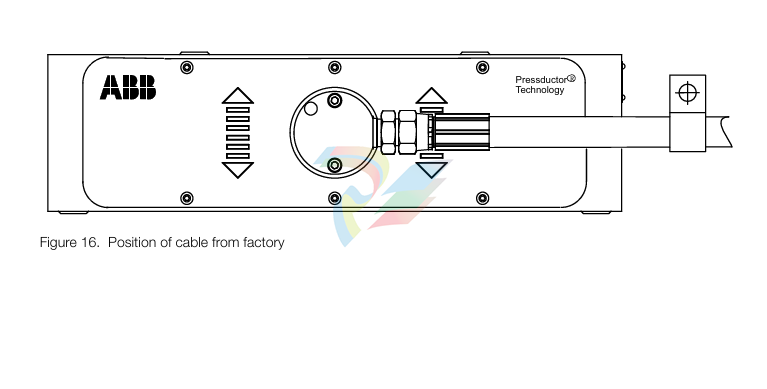
Cabling with protective hose shall be mounted so that the forces related to the weight of the cable/ hose do not act in the measuring direction of the load cell. A cable clamp is therefore necessary. If the load cell is prevented from movement in the measuring direction- it will shunt force, and the measured force will differ from the actual.
The favourable direction of the cable/hose is the horizontal direction to the left or right as indicated in Figure 16. Position of cable from factory page 20. This as possible forces in the longitudinal direction of the cable/hose due to temperature, will act perpendicular to the measuring direction of the load cell (the direction in which the load cell is insensitive to loads).
For achievable cable directions, see Figure 17. Possible directions of cable for PFCL 201CE page 21. The direction of the cable and protective hose can be changed by unscrewing the two screws in the connection box and turning the cable to a suitable direction. Make sure to re-install the screws in the connection box.
General
The actual procedure for commissioning a load cell is simple, provided that the load cells and cables have been properly installed. Commissioning of the control unit is described in the relevant chapter of the control unit manual.
Check the following:
• that the load cells have been correctly installed and aligned
• that all screws have been tightened to the correct torque
• that all cables are correctly installed and connected
• that all connectors are plugged in
Preparatory Calculations
To be able to set the correct measuring range, the measurement force per load cell FR/2 at maxi mum tension T must be calculated. Each load cell is subjected to half the total measurement force FR. This calculation must be done before commissioning can begin. Calculation of FR is described in 2.5 Mounting Arrangement.
Maintenance
General
Strip Tensiometer Systems with Pressductor® load cells are extremely reliable and do not require daily servicing. As a preventive measure, checks should be done periodically on all parts subject to mechanical wear.
Preventive Maintenance
Check mounting screws and tighten if necessary.
The gaps between load cell and plates should be checked to ensure that they do not get clogged with dirt, causing shunt force past the load cell. Clean the gaps with compressed air if necessary. The cable between the load cell and the junction box is subjected to possible damage and should be checked and replaced if necessary.
-
Adlink NuPRO-E42 51-41808-0A30 Industrial Motherboard
-
ADLINK IH61-AA400-A4A1E (IMB-M40H) Industrial Motherboard
-
ADLINK PCIe-GIE64+ GigE Vision Frame Grabber Card
-
ADLINK MXC-6322D(G) Industrial Fanless Computer working
-
ADLINK CPCI-7300 32-CH 80 MB/s High-Speed Digital I/O Module
-
Adlink cPCI-8168 Advanced 6U Compact PCI 8-Axis Motion Controller
-
Adlink VME CPU Board cPCI-6626/2710/M4G
-
ADLINK cPCI-R6200 high-performance 6U CompactPCI Rear Transition Module (RTM)
-
Adlink cPCI-7248 48-CH Opto-22 Compatible Digital I/O Module
-
ADLINK DLAP-211-JNX/DLAP-211-JT2/ DLAP-211-Nan
-
ADLINK cPCI-3544 4-Port RS-422/485 Isolated Serial Communications Card
-
Hirschmann MSP30-16040SCZ999HHE2A Manage the basic unit of the industrial DIN-Rail switch
-
Hirschmann MSP30-16040SCY999HHE2A
-
Hirschmann RS20-0400S2S2SDAEHC09.0.00 Management-type industrial fast Ethernet switch
-
Hirschmann Belden OCTOPUS OS20-002800T5T5T5-TBBY999GMSE3S Manageable industrial Ethernet switch
-
HIRSCHMANN OS20-000800T5T5T5-TBBU999H5SE2S
-
HIRSCHMANN RS20-0800M4M4SDAEHC09.0.14 industrial switch
-
Hirschmann RS20-0800T1T1SDAUHC RS20-0800T1T1SDAE
-
Hirschmann MSM20-M2M2M2M2SY9HH9E99.9 Fast Ethernet Media Module
-
HIRSCHMANN MAR1040-4C4C4C4C9999SMMHPHH Managed Etherne
-
HIRSCHMANN MAR1040-4C4C4C4C9999SMMHPHH Managed Etherne
-
HIRSCHMANN MAR1040-4C4C4C4C9999SM9HRHH Managed Etherne
-
HIRSCHMANN MAR1040-4C4C4C4C9999SM9HPHH05.1.00 industrial switch
-
HIRSCHMANN MM20-P9P9M2T1SAHH Fast Ethernet media module
-
HIRSCHMANN MM20-P9T1T1T1SAHH hot-swappable hybrid media module
-
HIRSCHMANN MM20-Z6Z6T1M2SAHH Fast Ethernet media module
-
HIRSCHMANN MM20-Z6M2M2T1SAHH Fast Ethernet media module
-
HIRSCHMANN MM20-Z6Z6Z6T1SAHH media module.
-
HIRSCHMANN MM20-Z6T1T1T1EBH Fast Ethernet media card.
-
Hirschmann MM20-Z6T1T1T1SAHH Hot-swappable fast Ethernet media module
-
Hirschmann MM20-Z6Z6M2M2EBH media module
-
HIRSCHMANN MM20-Z6Z6T1T1SZHH Technical Datasheet & SEO Guide
-
HIRSCHMANN MM20-Z6Z6T1T1EBH Technical Datasheet & Overview
-
HIRSCHMANN MM20-Z6Z6Z6Z6SZHH Media Module
-
HIRSCHMANN MM20-M4M2M2T1SAHH Media Module
-
HIRSCHMANN MM20-M4T1M2T1SAHH Media Module
-
HIRSCHMANN MM20-M2M2T1T1EBH Media Module
-
HIRSCHMANN MM20-M2M2T1T1SAHH Media Module
-
HIRSCHMANN MM20-M2T1T1T1TAHH Media Module
-
HIRSCHMANN MM20-M2T1T1T1EBH Media Module
-
HIRSCHMANN MM20-M2T1T1T1SAHH Media Module
-
HIRSCHMANN MM20-M2T1T1T1SAHH Media Module
-
HIRSCHMANN MM20-M2T1T1T1SAHH Media Module
-
HIRSCHMANN MM20-M2T1T1T1SAHH Media Module
-
HIRSCHMANN MM20-M2M2M2M2EBH Industrial Ethernet Media Module
-
HIRSCHMANN RS20-1600S2S2SDAEHH09.0.14 Ethernet switch
-
HIRSCHMANN MSM20-M2M2T1T1SY9HH9E99.9.99
-
HIRSCHMANN MSM20-M2M2M2M2SY9HH9E Ethernet media modul
-
HIRSCHMANN SPIDER-PL-20-05T1999999TWVHHHH Industrial Ethernet Rail Switch
-
Hirschmann SPIDER-PL-20-07T1M2M299TWVHHHH Industrial ETHERNET Rail Switch
-
Hirschmann (Belden) RS20-1600M2M2SDAEHC09.1.00 DIN-rail managed industrial Fast Ethernet switch
-
Hirschmann (Belden) RS30-1602O6O6TDAPHC09.1.00 DIN-rail managed industrial Ethernet switch
-
Hirschmann RS30-2402O6O6SDAP Ethernet switch
-
Hirschmann (Belden) RS30-2402O6T1SDAPHH09.0.13 DIN-rail industrial Ethernet switch
-
Hirschmann (Belden) RS30-2402O6T1SDAPHH09.0.13 DIN-rail industrial Ethernet switch
-
Hirschmann (Belden) SPIDER-PL-20-04T1S29999TY9HHHH Ethernet DIN-rail switch
-
HIRSCHMANN RS20-1600T1T1SDAUHX Switch
-
HIRSCHMANN BRS42-0012OOOO-SPCZ99HHSES industrial switch
-
Hirschmann RS20-0800S2S2TDHPHH09.0.14 Fast Ethernet DIN rail switch.
-
HIRSCHMANN MM20-Z6Z6M2M2SAHH Hybrid Fast Ethernet Media Module
-
HIRSCHMANN MM20-Z6Z6T1T1SAHH hot-swappable hybrid Fast Ethernet Media Module
-
HIRSCHMANN MM20-P9P9T1T1SAHH Hybrid Fast Ethernet Media Module
-
HIRSCHMANN MM20-M4T1T1T1SAHH Hybrid Fast Ethernet Media Module
-
HIRSCHMANN MM20-M4M4T1T1SAHH Hybrid Fast Ethernet Media Module
-
HIRSCHMANN MM20-M2M2M2M2SZHH Ethernet media module
-
HIRSCHMANN MM20-M2M2M2M2SAHH Ethernet media module
-
HIRSCHMANN MM20-T1T1T1T1EBH 4-port Fast Ethernet Copper Cable Media Module
-
HIRSCHMANN MM20-T1T1T1T1SAHH 4-port Fast Ethernet Copper Cable Media Module
-
HIRSCHMANN MM20-Z6Z6EBH Hot-swappable fast Ethernet media module
-
HIRSCHMANN MM20-Z6Z6SAHH Ethernet media module
-
HIRSCHMANN MM20-Z6Z6Z6Z6EBH Industrial Media Module
-
MSM40-T1T1T1TZ9HH9E99.9.99 HIRSCHMANN Switch
-
HIRSCHMANN MS20-0800SAAEHC / MS20-0800SAAEHC0 8-port modular Layer 2 management Ethernet switch
-
Hirschmann RSPM20-4T14T1SZ9HHS9 Switch RSPM20-4T14T1SZ9HHS9
-
HIRSCHMANN RS20-1600M2M2SDAEHH09.1. RS20/30/40 Managed Switch configurator
-
HIRSCHMANN RS20-1600M2M2SDAEHX09.0.00 Ethernet switch
-
HIRSCHMANN BELDEN SPIDER-PL-20-07T1M2M299TY9HHHH / SPIDERPL2007T1M2M299TY9HHHH
-
HIRSCHMANN MM3-1FXS2/3TX1 Switching Board Module
-
HIRSCHMANN RSPE30-24044O7T99-SCCV999HHSI2SXX.X.XX Switch
-
HIRSCHMANN RSPE30-24044O7T99-ECCP999HHSE2A08.1.00 Industrial-grade fanless management-type Ethernet switch
-
HIRSCHMANN RS30-1602OOZZSDAEHC09.1.00 DIN-rail-mounted managed Layer 2 Ethernet switch
-
HIRSCHMANN MACH104-20TX-F Managed 24-port Full Gigabit 19" Switch
-
HIRSCHMANN Switch RS20-0800M4M4SDAE
-
Hirschmann RS30-1602O6O6SDAEHH09.1. Management-type Ethernet switch
-
Hirschmann RS30-1602OOZZSDAEHC09.0.10 Open rack-style Ethernet switch
-
HIRSCHMANN RSPE30-24044O7T99-SCCV999HHSI2SXX.X.XX High-Availability Seamless Redundancy
-
HIRSCHMANN RSPE30-24044O7T99-SCCZ999HHSE2A DIN-rail Ethernet switch
-
HIRSCHMANN MM2-4TX1-EEC switch
-
HIRSCHMANN MSM40-T1T1T1T1TZ9HH9E99.9.99 Module
-
HIRSCHMANN RS20 Rail Switch RS20-0400S4T1SDAEHC07.1.01
-
HIRSCHMANN M4-FAST8-SFP Fast Ethernet media module
-
HIRSCHMANN RS20-0400M2T1SDAP Managed Fast-Ethernet-Switch
-
HIRSCHMANN BELDEN SPIDER II 8TX/1FX EEC Industrial Ethernet Rail Switch
-
HIRSCHMANN MM3-2FXS2/2TX1
-
HIRSCHMANN RS2-4TX/1FX EEC Industrial Ethernet Rail Switch 2
-
RS30-0802O6O6SDAEHC09.0.10 HIRSCHMANN Switch
-
HIRSCHMANN m4-8TP-RJ45 Ethernet Media Module
-
HIRSCHMANN MSP30-24040SCZ9URHHE3A switch
-
Hirschmann rack MS30-1602SAAPHC
-
HIRSCHMANN RS2-FX/FX Industrial Switch Module
-
Rs1txfx - Hirschmann - Rs1-Tx/Fx Rail Switch
-
RS20-0800S2S2SDAEHC09.1.00 HIRSCHMANN Commutator
-
Hirschmann EAGLE20 TX/TX Industrial Security Router
-
Hirschmann SPIDER-SL-20-04T1S29999SY9HHHH Industrial Switch
-
HIRSCHMANN MAR1040-4C4C4C4C9999SMMHRHHXX.X. Gigabit Ethernet Switch configurator
-
Hirschmann MAR1040 Industrial Switch
-
HIRSCHMANN BELDEN RS30-1602O6O6SDAE
-
Hirschmann RS20-1600M2M2SDAUHC Ethernet DIN rail switch
-
HIRSCHMANN OCTOPUS24M industrial switch
-
HIRSCHMANN RS20-1600T1T1SDAE Management-type Ethernet switch
-
HIRSCHMANN RS20-1600T1T1SDAUHH industrial switch
-
HIRSCHMANN RS20-0800M2M2SDAPHC09.0.04 switch
-
Hirschmann MR 8-03 24V DC Industrial Modular Bridge/Router
-
HIRSCHMANN RS20-0400M2T1SDAPHC08.0.01 Managed Switch
-
MACH1130 Hirschmann Industrial Switch
-
HIRSCHMANN 943824-002 SPIDER 5TX Industrial Ethernet Switch
-
HIRSCHMANN RS30-0802O6O6SDAEHC09.1.00 Managed Industrial Switch
-
HIRSCHMANN RS20-0400M2M2TDAEHC04.0.01 Industrial Switch
-
HIRSCHMANN BRS20-0600Z6Z6-STCZ99HHSES Industrial Switch
-
HIRSCHMANN MACH104-20TX-FR-L3P Industrial Ethernet Switch
-
HIRSCHMANN RS40-0009CCCCEDBPHH06.0.01 Industrial Switch
-
HIRSCHMANN RS2-3TX/2FX EEC Industrial Ethernet Switch
-
Hirschmann MACH 1020/1030 Fast/Gigabit Rack Mount Switches
-
HIRSCHMANN RS20-0800M2M2SDAPHC09.0.14 Industrial Switch
-
HIRSCHMANN RS20-1600T1T1SDAEHC09.0.04 Industrial Switch
-
HIRSCHMANN RSB20-0800T1T1EAABHH Industrial Switch
-
HIRSCHMANN MACH4002-48+4G-L3E Industrial Backbone Switch
-
HIRSCHMANN RS20-0400S2T1SDAE Industrial Managed Switch
Add: High-tech Software Park, Xiamen City, Fujian Province
Mobile: +86-17750019513(WhatsApp)
Email: yy4291644@gmail.com
Website: https://www.abb-sis.com
.jpg)
.jpg)
.jpg)
.jpg)
.jpg)
.jpg)

-
Adlink NuPRO-E42 51-41808-0A30 Industrial Motherboard
-
ADLINK IH61-AA400-A4A1E (IMB-M40H) Industrial Motherboard
-
ADLINK PCIe-GIE64+ GigE Vision Frame Grabber Card
-
ADLINK MXC-6322D(G) Industrial Fanless Computer working
-
ADLINK CPCI-7300 32-CH 80 MB/s High-Speed Digital I/O Module
