

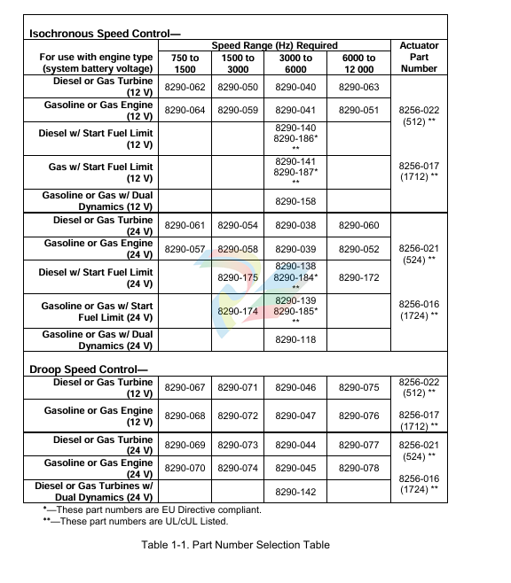
Woodward 8290-189-EPG-installation-manual 8290-044
outside diameter of the gear should be set to approximately 1.0 mm (0.04”) at the
closest point (radial runout). Using the pickup with small gears may require
spacing as close as 0.25 mm (0.010”).
If you cannot measure the gap directly, it can be set in this manner: with the
prime mover shut down, turn the pickup in (clockwise) until it touches the outside
diameter of a tooth. Then back out the pickup (counterclockwise) approximately
three-quarters of a turn. Run the gear slowly through 360 degree rotation to
check the clearance of the pickup. When the gap is set, tighten the jam nut
securely against the housing or bracket.
The standard pickup models require mating connectors, MS 3102R-18-3P. The
connectors are not furnished with the pickup, but may be ordered from
Woodward if desired. See manual 82510. Magnetic Pickups and Proximity
Switches for Electronic Controls, for more information
Wiring Instructions
Use a wiring diagram for the specific part number of your EPG system to make
all wiring connections. The wiring diagram is available from Woodward. Typical
wiring is shown in Figure 2-5.
Make all connections using insulated terminals. The wiring from actuator to
speed control and from the battery to the speed control must be as short as
possible. Maximum wiring lengths are:
Maximum Wiring Length Chart
EPG Model
14 AWG
(2 mm²)
Maximum Wire Length
12 AWG
(3 mm²)
512/1712
10 ft (3 m)
524/1724
20 ft (6 m)
35 ft (11 m)
75 ft (23 m)
The fuse and switch or circuit breaker must be in the non-grounded battery lead.
Use a fuse or circuit breaker as specified in the Switch and Fuse Requirements
Chart. Do not use a fuse of higher current rating. Starter relays make good EPG
power switches.
Installation Checks
Checks for all Applications
The following steps check only the speed control and actuator, which must work
correctly before paralleling the generator. Since most faults appear when the
prime mover is first run, this step-by-step approach eliminates most problems
before they occur. The main part of Chapter 5 (Troubleshooting) is doing these
checks.
If a Load Sensor is used, temporarily remove the wires at speed control terminals
11 and 12 and temporarily jumper terminals 11 to 12. The generator must not be
paralleled during these tests. If a Ramp Generator is used, temporarily remove
the wire at speed control terminal 10. If a capacitor is connected to terminal 10 to
provide a ramp between unloaded and loaded, it must be removed during this
test or calibration. Leave the idle-rated switch wiring connected. Do the checks in
the order indicated. Terminal numbers in this section refer to the speed control.
Check that all electrical connections are correctly made and terminal screws
are tight; the magnetic pickup is properly installed and the jam nut is tight;
the actuator and linkage are securely fastened. If start-fuel limit is present,
turn the adjustment fully clockwise during these tests. If dual dynamics are
present, set the switch closed for slow dynamics.
2. Do not start the prime mover now. Turn on governor power. If the fuse or
breaker opens as soon as power is applied, the battery polarity (terminals
14 and 15) is probably reversed. The actuator shaft can jump when power is
turned on, but must quickly come back to the minimum fuel position. Check
the battery voltage at terminal 1 (+) and 2 (–). It must be from 10 to 16 Vdc
for 512/1712 controls, and from 20 to 32 Vdc for 524/1724 controls.
Disconnect any wiring or jumper on terminal 7. Measure 7.2 ±1.0 V from
terminal 2 (–) to 7 (+) [terminals 2 (–) to 9 (+) for dual-dynamics control].
Reinstall the wiring to terminal 7 if voltage is correct. Do not use the control
if voltage is incorrect.
If idle speed is desired, connect a 50 kΩ potentiometer or fixed resistor to
terminals 9 and 10 as shown in the typical wiring diagram. To calculate the
value of a fixed resistor:
R = 17 kΩ
( Rated Speed
Idle Speed – 1 )
Put the idle-rated switch in the rated position or jumper terminals 9 and 10.
Measure the voltage from terminal 7 (+) to 2 (–). Put the idle-rated switch in
the idle position or remove the jumper. The voltage must increase. If it does
not increase, check the speed trim pot, if used, and the idle-rated switch
wiring.
If a signal generator with an isolated output is available, the failsafe and
actuator travel can be checked, Rated and idle speed can be preset. If a
signal generator is not available, skip to step 7.
Turn off governor power. Remove the magnetic pickup wires from terminals
5 and 6. Connect the signal generator to terminals 5 and 6. Set the output
between 2 and 10 Vrms. The wave form can be sine, square, or triangular.
Calculate the MPU frequency for idle and rated speeds (see part number
selection in Chapter 1).
Check Failsafe and Actuator Travel:
Set the signal-generator frequency to about half of idle speed. Set the idle
rated switch to rated. Turn the signal generator and governor power on. The
linkage must be at the maximum-fuel position. Except for Detroit Diesel
engines, verify that linkage travel is limited by the prime-mover fuel control,
not by the actuator stop. Turn the signal generator off and remove the
connections at terminals 5 and 6. The linkage should move to the minimum
-
SHINKAWA MODEL VM-5Z5,6,7 POWER SUPPLY UNIT
-
SHINKAWA MODEL VM-5Y1,2,3 RELAY MODULE UNIT
-
SHINKAWA MODEL VM-5P3 PHASE MARKER UNIT
-
SHINKAWA MODEL VM-53 DUAL COMMUNICATION UNIT
-
SHINKAWA MODEL VM-52 BOTTOM HOLD MONITOR
-
SHINKAWA MODEL VM-51 ROD DROP MONITOR
-
SHINKAWA MODEL VM-5R TACHOMETER
-
SHINKAWA MODEL VM-5S DUAL TACHOMETER
-
SHINKAWA MODEL VM-5A DUAL VALVE
-
SHINKAWA MODEL VM-5E DUAL CASE
-
SHINKAWA MODEL VM-5L COMPLEMENTARY INPUT
-
SHINKAWA MODEL VM-5N RAMP DIFFERENTIAL
-
SHINKAWA MODEL VM-5D DUAL DIFFERENTIAL
-
SHINKAWA MODEL VM-5T DUAL THRUST MONITOR
-
SHINKAWA MODEL VM-5C ECCENTRICITY MONITOR
-
SHINKAWA MODEL VM-5C ECCENTRICITY MONITOR
-
SHINKAWA MODEL VM-5M DUAL PATH MONITOR
-
SHINKAWA MODEL VM-5B DUAL ACCELERATION MONITOR
-
SHINKAWA MODEL VM-5B DUAL ACCELERATION MONITOR
-
SHINKAWA MODEL VM-5U DUAL SEISMIC MONITOR
-
SHINKAWA MODEL VM-55 VIBRATION MONITOR
-
SHINKAWA VM-742B1-5 VIBRATION MONITORING SYSTEM CARD
-
Shinkawa PSP-17B P-24-64A P-24-64B Circuit Board Module
-
SHINKAWA MGP-67 PCB
-
Shinkawa JBP-278 P-22-48A-1 P-22-48B-1 Circuit Board Module
-
Shinkawa VM-721B 18-CHANNEL RELAY MODULE
-
Shinkawa FRP-337 P-26-54A P-26-54B Circuit Board Module
-
Shinkawa WKN-142K2-2 Vibration Transmitter
-
SHINKAWA VL-202A08L-1012 Rotor Position Monitor Probe Sensor
-
Shinkawa CPP-128 P-26-74A P-26-74B Circuit Board Module
-
Honeywell 51402755-100 PROCESSOR CARD
-
Honeywell 51107595-100 Power
-
HONEYWELL 51304544-100 Control Board
-
HONEYWELL 51109919-100 BOARD
-
HHoneywell 51204160-175 Digital Input Module
-
Honeywell 51304754-150 High Level Analog Input Module
-
HONEYWELL 51304690-100 DIGITAL INPUT CARD
-
Honeywell 51401635-150 COMM CONTROL
-
HONEYWELL 51204174-175 MC-TAOY 52 ANALOG OUTPUT BOARD
-
HONEYWELL 51400596-100
-
HONEYWELL 51401291-100 board card
-
HONEYWELL 51401642-150 I/O LINK MODULE
-
Honeywell LCN‑E Hub Power Supply 38500148‑300
-
Honeywell LCN‑E Hub redundant 38500143‑202 Twisted‑pair LCN
-
Honeywell LCN‑E Hub non‑redundant,38500143‑102
-
Honeywell Enhanced Micro‑TDC‑3000 System Unit MX‑DTAC01K2
-
Honeywell Enhanced Micro‑TDC‑3000 System Unit MX‑DTAB01K2
-
Honeywell Enhanced Micro‑TDC‑3000 System Unit MT11‑520
-
Honeywell STI‑CE Smart Transmitter Interface 51304516‑150
-
Honeywell STI Smart Transmitter Interface 51304516‑100 MC‑PSTX02
-
Honeywell ulse Counter IOP 51304386‑100 MU‑PPIX02
-
Honeywell DO Digital Output IOP‑CE 51304487‑150 CE version
-
Honeywell DO Digital Output IOP 51304487‑100 MC‑PDOX02
-
Honeywell TDC‑3000 SOE DI IOP,51402625-175 MC‑PDIS12
-
Honeywell TDC‑3000 DI Digital Input IOP‑CE 51304485‑150
-
Honeywell TDC‑3000 DI Digital Input IOP 51304485‑100 MC‑PDIX02
-
Honeywell TDC‑3000 AO Analog Output IOP 51304757‑100 MU‑PAOX02
-
Honeywell TDC‑3000 TC Thermocouple IOP 51304756‑100 MU‑TAMT03
-
Honeywell TDC‑3000 51304755‑100 MU‑TAMR03
-
Honeywell TDC‑3000 LLAI Multiplex AI IOP,51304362‑150
-
Honeywell TDC‑3000 HLAI Analog Input IOP‑CE, 51304363‑150
-
Honeywell TDC‑3000 HLAI Analog Input IOP,51304363‑100.4‑20mA
-
Honeywell TDC‑3000 HPM Power Supply,51401731‑100
-
Honeywell TDC‑3000 Standard 1986.HPM High‑Performance PM CPU,51402362‑100
-
Honeywell TDC‑3000 APM Advanced Process Manager CPU,51304459‑100
-
Honeywell TDC‑3000 Standard 1986.PM Process Manager CPU,51304362‑100
-
Honeywell TDC‑3000 NIM Network Interface Module,51304481‑200
-
Honeywell TDC‑3000 NIM Network Interface Module 51304481‑100
-
Honeywell TDC‑3000 BASIC,LCN Terminator Resistor,30732052‑001.Coaxial
-
Honeywell TDC‑3000 BASIC,Hiway Coupler,30753732‑001
-
Honeywell TDC‑3000 BASIC,LEPIU Low‑Energy PIU,4DP7APCFA309
-
Honeywell TDC‑3000 BASIC,HLPIU High‑Level PIU,4DP7APCFA106
-
Honeywell TDC‑3000 BASIC,Multifunction Controller(TDC‑2000 DHW),4DP7MFA103
-
Honeywell TDC‑3000 BASIC,Extended Controller(TDC‑2000 DHW),4DP7AXA102
-
Honeywell TDC‑3000 BASIC,Basic Controller(TDC‑2000 DHW),4DP7BBA101
-
Honeywell 51305508‑100 TDC‑3000 BASIC,XLCNE2 LCN Extender
-
Honeywell TDC‑3000 BASIC,E‑PLCG PLC Gateway,51400997‑200
-
Honeywell TDC‑3000 BASIC,PLNM Plant Network Module,51401163‑100
-
Honeywell TDC‑3000 BASIC,CG Computer Gateway,80360206‑001
-
Honeywell TDC‑3000 BASIC,HG High‑Speed Gateway,51304526‑100
-
Honeywell TDC‑3000 BASIC,HM History Module,51191596‑200
-
Honeywell TDC‑3000 BASIC,HM History Module,51191596‑100
-
Honeywell TDC‑3000 BASIC,AM Application Module CPU,51401551‑800.K2LCN‑8
-
Honeywell TDC‑3000 BASIC,AM Application Module CPU,51401551‑600.K2LCN‑6
-
Honeywell TDC‑3000 BASIC,AM Application Module CPU,51401551‑400,K2LCN‑4
-
Honeywell TDC‑3000 BASIC,AM Application Module CPU,51401551‑300.K2LCN‑3
-
Honeywell TDC‑3000 BASIC,AM Application Module CPU,51401551‑200,K2LCN‑2
-
Honeywell TDC‑3000 BASIC,US Universal Station CPU,51401288‑200
-
Honeywell TDC‑3000 BASIC,US Universal Station CPU,51401288‑100
-
SHINKAWA VM-21P1 Signal Conditioner 0-50MM 24VDC
-
Shinkawa RiverNew Vibration Transducer VK202 Series
-
Shinkawa Electric VM-3E2 Vibration Monitor Module
-
Shinkawa JBP-47 P-22-48A-1 / P-22-48B-1 Circuit Board Module
-
Shinkawa MODEL VM-5K DUAL VIBRATION MONITOR
-
Shinkawa CMU-15A (CMU15A) Industrial Camera Controller
-
Shinkawa CMU-13A CMU13A Industrial Camera Controller
-
Shinkawa EFU-10 (EFU10) Spark Generator Unit
-
Shinkawa UTC-1000 ZUP-02C Board
-
Shinkawa MDP-89 MDP89 P-24-674A P-24-674B Circuit Board Module
-
Shinkawa CB-1011005001 Signal Cable Assembly
-
SHINKAWA VL-202A08L-1002 Sensor VL-08020L01 Probe Cable F84N1695
-
Shinkawa VK-202A2 Driver & VL-202A08L-1A72 Proximity Sensor Probe
-
SHINKAWA VM-703B VIBRATION MONITORING SYSTEM CARD 2R05-002-P001C
-
Shinkawa BH-150-03 Signal Conditioner / Preamplifier Unit
-
Shinkawa BH-150 Signal Conditioner / Preamplifier Unit
-
Shinkawa Electric VM-3D2 Thrust Monitor Module
-
Shinkawa LCU-37 Monitoring module
-
Shinkawa LCU-44B-06 Local Control Unit Module
-
ABB 3BHE039724R2643 PPD513 high-performance programmable controller module
-
Samsung SSAS21-RTD Resistance Temperature Detector Input Module
-
Samsung SSAS21-AI Analog Input Module
-
Samsung SSAS21-DO Digital Output Module
-
Samsung SSAS21-DI Digital Input Module
-
Samsung SSAS21-CPU Central Processing Unit Module
-
Samsung SMTB-RTD RTD/TC Terminal Board
-
Samsung SMTB-AI Analog Input/Output Terminal Board
-
Samsung SMTB-DO Digital Output Terminal Board
-
Samsung SMTB-DI Digital Input Terminal Board
-
SAMSUNG SMBK-12 IOU Rack Backplane
-
SAMSUNG SMBK-08 IOU Rack Backplane
-
SAMSUNG SMPS-08 Rack Power Module
-
SAMSUNG SMCOM-08 Communication Expansion Card
-
SAMSUNG SMPI-8 Pulse Count Input Module
-
SAMSUNG SMTC-8 Thermocouple Input Module
-
SAMSUNG SMAOC-12 Analog Output Module (12CH)
-
SAMSUNG SMAOC-8 Analog Output Module (8CH)
-
SAMSUNG SMAIC-12 Analog Current Input Module (12CH)
-
SAMSUNG SMRTD-8 RTD Pt100 Temperature Input Module (8CH)

Add: High-tech Software Park, Xiamen City, Fujian Province
Mobile: +86-17750019513(WhatsApp)
Email: yy4291644@gmail.com
Website: https://www.abb-sis.com
.jpg)
.jpg)
.jpg)
.jpg)
.jpg)
.jpg)

-
SHINKAWA MODEL VM-5Z5,6,7 POWER SUPPLY UNIT
-
SHINKAWA MODEL VM-5Y1,2,3 RELAY MODULE UNIT
-
SHINKAWA MODEL VM-5P3 PHASE MARKER UNIT
-
SHINKAWA MODEL VM-53 DUAL COMMUNICATION UNIT
-
SHINKAWA MODEL VM-52 BOTTOM HOLD MONITOR
