

Woodward easYgen-400 Operation Manual Genset Control
easYgen-400
Operation Manual
Genset Control

Rev. Date Editor Changes
F 2023-08 MK NEW Software Version 2.1.0.8
•Suitable for new LCD display •
E 2021-06 MK NEW Software Version 2.1.0.7
•needed ToolKit-SC Version 1.5.1.5 or higher •
NEW features & functions
•Added output ports: 27 Preheat until safety, 28 Preheat until •
warming, 29 Preheat until cranking
Corrections/Repairs
•None •
D 2020-11 TM NEW Software Version 2.1.0.6
•needed ToolKit-SC Version 1.5.1.3 or higher •
NEW features & functions
•Support for HATZ ECU •
Corrections/Repairs
•None •
C 2020-11 TM NEW Software Version 2.1.0.5
NEW features & functions
• ID 835 Enumeration "emergency shutdown" function for discrete •
inputs
• ID 846 Action (alarm class) from analog inputs monitoring is now •
configurable
• ID 1099 Additional logic for maintenance counters •
• ID 1098 Semi-Auto mode for AMF start •
• ID 1103 Unbalanced load alarm •
Corrections/Repairs
• ID 837 Breaker logic "constant" de-energizes with breaker alarm •
• ID 931 Corrected Volvo ECU 50/60 Hz selection
Rev. Date Editor Changes
• ID 1000 Reference values for rated "active power" and "reactive •
power"
B 2019-05 PW NEW Software Revision 2.0.0.1 and ToolKit-SC version 1.5.0.4
Corrections/Repairs
•Fixed the following in HMI software: •
◦fixed the version name to 4 digits; ◦
◦possibility to close GCB when engine not running; ◦
◦kvar spelling; ◦
◦ impossibility to mute the horn with easYlite-200; ◦
◦HMI user defined sensor curves displaying messy codes in ◦
other languages
◦after gen closed, if changed breaker close delay by Toolkit-◦
sc, 6550 countdown error occurred in HMI;
◦when change to OEM plant theme and Terminal users ◦
theme, press close/open button in manual mode, error
occurred in breaker page;
◦Horn/Alarm Acknowledge / Alarm reset function ◦
◦"Traditional Chinese" implemented ◦
◦changed name easYgen400/easYgen1400 to easYgen-400/ ◦
easYgen-1400 in controller information page;
◦status LED not turning on if the "Conventional Engine" was ◦
selected, easYgen and genset in STOP condition, START
button pressed;
◦maintenance counter resetting ◦
◦Polish translation errors ◦
◦modified configuration of auto test mode, including number ◦
of input ports, LED display order, and level sensor changed
from flexible sensor to resistor type sensor;
◦ J1939 standard and setpoint idle ◦
◦Volvo EMS2 50/60Hz rated speed selection ◦
◦overload monitoring not using the "return" value; ◦
◦Volvo EMS2 rated frequency selection and rated speed ◦
modification;
◦mains breaker warning in MAN mode; ◦
◦operation mode changing from MAN with closed GCB to ◦
MCB;
◦breaker status in MAN mode; ◦
◦removed all ECU types with Modbus; ◦
◦removed “Baud rate and Modbus slave ID” parameters; ◦
◦parameter naming change: in order to align with ToolKit, ◦
changed “Current” to “Limit” and “Low fuel level” to “Fuel
level warning” in HMI parameter config screen;
•Fixed the following in ToolKit-SC
Rev. Date Editor Changes
◦fixed the version name of 2 digits displayed on ToolKit to 4 ◦
digits;
◦removed WWDMODEM-3G related parameters; ◦
◦removed “emergency stop input”; ◦
◦removed “Baud rate and Modbus slave ID”parameters; ◦
◦removed all ECU types with Modbus. ◦
A 2018-11 PC Describes device implemented software version 1.8 and
ToolKit-SC version 1.4.0.2
Additional markings
To highlight instructions, results, lists, references, and other elements, the following
markings are used in these instructions:
Marking Explanation
__▶ Step-by-step instructions
⇨ Results of action steps
╚═▷ References to sections of these instructions and to other
relevant documents
• Listing without fixed sequence
»Buttons« Operating elements (e.g. buttons, switches), display
elements (e.g. signal lamps)
»Display« Screen elements (e.g. buttons, programming of function
keys)
[Screen xx / Screen xy /
Screen xz] ...
Menu path.
The following information and setting refer to a page on
the HMI screen or ToolKit located as described here.
Some parameters/settings/screens are available only
either in ToolKit or on the HMI/display
1.2 Copyright And Disclaimer
Disclaimer
All information and instructions in this manual have been provided under due
consideration of applicable guidelines and regulations, the current and known state of the
art, as well as our many years of in-house experience. Woodward assumes no liability for
any damages due to:
•Failure to comply with the instructions in this manual •
• Improper use / misuse •
•Willful operation by non-authorized persons •
•Unauthorized conversions or non-approved technical modifications •
•Use of non-approved spare parts •
The originator is solely liable for the full extent for damages caused by such conduct. The
obligations agreed-upon in the delivery contract, the general terms and conditions, the
manufacturer’s delivery conditions, and the statutory regulations valid at the time the
contract was concluded, apply.
Copyright
This manual is protected by copyright. No part of this manual may be reproduced in any
form or incorporated into any information retrieval system without written permission of
Woodward GmbH.
Delivery of this manual to third parties, duplication in any form - including excerpts - as
well as exploitation and/or communication of the content, are not permitted without a
written declaration of release by Woodward GmbH.
Actions to the contrary will entitle us to claim compensation for damages. We expressly
reserve the right to raise any further accessory claims
1.3
Service And Warranty
Opening the device will nullify any warranty
Any such unauthorized modifications
•
• constitute "misuse" and/or "negligence" as per the product warranty
•
• thereby exclude warranty coverage for any resulting damage, and
•
• invalidate product certifications or listings.
Our Customer Service is available for technical information. Please see page 2 for contact
details.
In addition, our employees are interested in any new information and experiences that
arise from usage and could be valuable for improving our products.
1.4
1.4.1
Safety
Intended Use
The easYgen unit has been designed and constructed solely for the intended use
described in this Operation Manual and – with even more details – in the Technical
Manual.
•
• Intended use requires operation of the control unit within the range outlined in the
written specifications.
Steps to be taken for commissioning are outlined in the Technical Manual. •
• Intended use includes compliance with all instructions and safety notes presented in •
this manual.
•Any use which exceeds or differs from the intended use shall be considered improper •
use.
•No claims for any kind for damage will be considered if such claims result from •
improper use.
1.4.2 Personnel
This manual specifies the personnel qualifications required for the different areas of work,
listed below:
•Well trained for electrical installations. •
•Aware of the local safety regulations. •
•Experienced in working with electronic measuring and control devices. •
•Allowed to manage the controlled (engine/generator) system. •
The workforce must only consist of persons who can be expected to carry out their work
reliably. Persons with impaired reactions due to, for example, the consumption of drugs,
alcohol, or medication are prohibited.
When selecting personnel, the age-related and occupation-related regulations governing
the operating location must be observed
System Overview
General notes
The easYgen is a stand-alone genset controller with measuring, monitoring, and breaker
control functionality. It comes with an easily mountable plastic housing covering a
thoroughly tested electronic-electrical system.
Display and buttons of the HMI offer access to states and values, as well as access to the
application. Password protection enables the assignment of multiple operation access
levels. Remote access, monitoring, visualization, and configuration are possible via
integrated interfaces. Communication between easYgens using PLC control or as a
network member offers an enhanced system management range; additionally supported
by easy to implement accessories
2.1
2.2
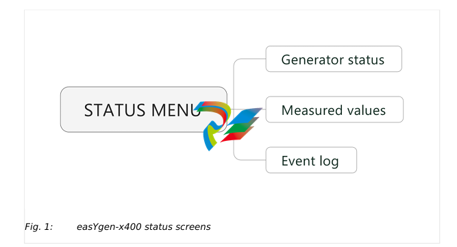
HMI Status Screens
HMI displays the following status screens:
•
• Status (home)
•
• Generator
•
• Load
•
• Engine 1
•
• Engine 2
•
• Status
•
• Alarm
•
• home screen etc.
ToolKit-SC Status Screens
General notes
ToolKit-SC lets you access status information via the following screens
Items Parameters Description
Engine info Engine speed, Battery volt, Charger volt D+
Sensor info Engine temp, Oil pressure, Fuel level Selection of ECU
data via J1939.
More info Coolant pressure, Coolant level,Fuel pressure, Fuel
temp, Turbo pressure, Oil temp, Inlet temp, Fuel
consume, Exhaust temp, Total consume
Alarms Current Alarms and Warning Lists of current
alarms and
warnings
(Digital )Inputs 01 High temperature shutdown, 02 Low oil pressure
shutdown, 10 Start request in AUTO, 11 Fuel level
warning, 12 Coolant level warning
(Digital) Outputs 02 Stop solenoid, 03 Idle control, 05 Close GCB, 06
Fuel relay, Start relay
Accumulation (run) Time, Starts
Next maintenance
time
Time
Engine hours Time
Generator status Gen status
Module info will be moved to Event log page
Items Parameters Description
Electricity quantity
Mains-/
Generator L1. L2. L3. L1-2. L2-3. L3-1. L1Phase, L2Phase, L3Phase, Frequency
Current (A) L1. L2. L3
Active power (kW) L1. L2. L3. Total
Reactive power (kvar) L1. L2. L3. Total
Apparent power (kVA) L1. L2. L3. Total
Power factor L1. L2. L3. Avg
Ext. Analog Inputs
[PARAMETER / STATUS MENU / Ext. analog inputs]
Items Parameters Description
Expansion AIN24 {X} {X}: 1 or 2
Cylinder Temp {Y} (in °C and °F) {Y}: 1 or 22
Exhaust Temp {Z} (in °C and °F) {Z}: 1 or 2
Sensor {N} {N}: 15 or 24
Event Log and Version
[PARAMETER / STATUS MENU / Event log and version]
Items Parameters Description
Module Info Model, Hardware Version, Software Version, Issue Date
Event log Fixed view of:
No., Event type
Columns "move behind" visible part of the screen:
Event Item, Date, Time,
((Mains control is not supported by this model, so all "Mains" values
are"0":))
Mains Uab (V) / Ubc (V) / Uca (V), Mains Ua (V), Mains Ub (V), Mains
Uc (V), Mains f (Hz),
Gens Uab (V) ..., Gens Ua (V) ..., Gens f(Hz),
Current Ia (A) ...,
Power (kW),
Speed (r/min),
Temp. (°C),
Press. (kPa),
Volt. (V)
Event log report
table. Showss the
99 latest events
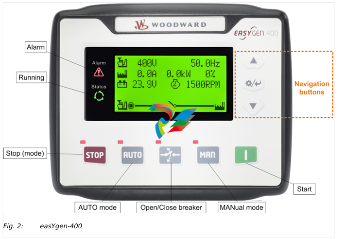
Icons Keys Description
STOP Auto/Manual mode: Stops running generator
Stop mode: Resets alarm
Lamp test (press at least 3 seconds)
Notes
During stopping process, press this button again to stop generator
immediately.
I (START) MANual mode: Start genset
MAN (Manual Mode) Press this key and the controller enters into MAN mode
AUTO (Automatic Mode) Press this key and the controller enters into AUTO mode
Open/Close breaker Release breaker control in MAN mode.
The navigation button "Up/Increase" is used to close the GCB
3.2.1
3.3
Alarm Acknowledgment
General notes
The alarm acknowledge handling is valid for following alarm classes
•
• Shutdown
•
• Trip/Stop
•
• Trip
Mute Horn
Any new active alarm activates the horn and is made visible by the flashing Alarm LED.
After pressing the "Down/Decrease" button, the horn is deactivated and the Alarm LED
changes from flashing to constantly active and stays active as long as any alarm is
present. An additional active alarm reactivates the horn and the Alarm LED starts flashing
again.
Stop by alarm
The operation mode automatically changes to STOP if a stopping alarm is active
(»Shutdown« or »Trip/Stop«).
Acknowledge alarm
In case of alarm condition, pressing the STOP button will reset the alarm.
Operation Modes
General notes
The easYgen offers three operation modes:
•
• AUTO
•
• MANUAL (MAN)
•
• STOP
•
• ... and an internal (non) operating phase during the start of the device itself
The operation mode can be initiated – provided the current settings allow for this
function:
•
• directly by pressing the respective button on the front panel
•
• directly by click on the respective button on the ToolKit-SC remote screen
•
• via discrete inputs
•
• via interface
3.3.1
General notes
In operation mode AUTO, both genset and breaker are under easYgen control. The start
and stopping of the engine is managed automatically, along with opening/closing the
breaker.
•
• supply load by generator
•
• start the engine
•
• stop the engine
3.3.2
Operation Mode MANual
General notes
In operation mode MANual, both genset and breakers are independent of each other
under easYgen control.
The starting and stopping of the engine are managed using the same procedure as in
AUTO mode but without breaker control. Breakers can be opened and closed without
taking care of load or genset state!
3.3.3
Operation Mode STOP
General notes
In operation mode STOP, the breaker is open and the engine is not running.
3.4
3.4.1
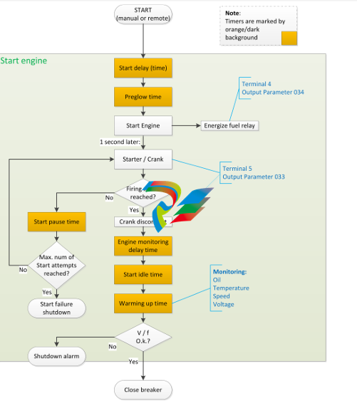
START/STOP Operation
Start engine to supply load
The AUTO Start procedure is going through sub procedures with own timers
3.5
Pressing
can stop the running generator as described above.
Transition Procedures
3.5.1
Disconnect during cranking
There are three conditions under control to abort the starting of the engine:
•
• speed sensor
•
• generator frequency
•
• engine oil pressure
They can be used separately or in combinations.
We recommend selecting all three at the same time: engine oil pressure together with
speed sensor, and generator frequency. This allows for an immediate separation of the
starter motor from the engine. Additionally, crank disconnect can be checked exactly.
When set to speed sensor, ensure that the number of flywheel teeth is the same as
setting.
5 Glossary and List of Abbreviations
CB Circuit Breaker
CT Current Transformer
DI Discrete Input
DO Discrete (Relay) Output
ECU Engine Control Unit
FMI Failure Mode Indicator
GCB Generator Circuit Breaker
GOV (speed) Governor; rpm regulator
HMI Human Machine Interface e.g., a front panel with display and
buttons for interaction
I Current
MCB Mains Circuit Breaker
MPU Magnetic Pickup Unit
N.C. Normally Closed (break) contact
N.O. Normally Open (make) contact
NC Neutral Contactor
OC Occurrence Count
Operation In (general) operation.
State when the genset is running according to the selected
mode, all parameters are in allowed values and ranges, and
without OPEN requests or alarms. Somehow "waiting for next
occurrence".
P Real power
P/N Part Number
PF Power Factor
PT Potential (Voltage) Transformer
Q Reactive power
S Apparent power
S/N Serial Number
SPN Suspect Parameter Number
V Voltage
Index
A
Alarms
Classes . . . . . . . . . . . . . . . . . . . . . . . . . . . . . . . . . . . . . . . . . . . . . . . . . . . . . . . . . . . . . . . . . . . . . . . . . . . . . . . . . . . . . . . . . . . . 25█
Shutdown Alarms . . . . . . . . . . . . . . . . . . . . . . . . . . . . . . . . . . . . . . . . . . . . . . . . . . . . . . . . . . . . . . . . . . . . . . . . . . . . . . . . . . . . . . . . . . . . 26█
C
Contact person . . . . . . . . . . . . . . . . . . . . . . . . . . . . . . . . . . . . . . . . . . . . . . . . . . . . . . . . . . . . . . . . . . . . . . . . . . . . . . . . . . . . . . . . . . . . 9█
Customer Service . . . . . . . . . . . . . . . . . . . . . . . . . . . . . . . . . . . . . . . . . . . . . . . . . . . . . . . . . . . . . . . . . . . . . . . . . . . . . . . . . . . . . . . . . . . . 9█
F
Functions . . . . . . . . . . . . . . . . . . . . . . . . . . . . . . . . . . . . . . . . . . . . . . . . . . . . . . . . . . . . . . . . . . . . . . . . . . . . . . . . . . . . . . . . . . . . 12█
I
Intended use . . . . . . . . . . . . . . . . . . . . . . . . . . . . . . . . . . . . . . . . . . . . . . . . . . . . . . . . . . . . . . . . . . . . . . . . . . . . . . . . . . . . . . . . . . . . 9█
K
Keys . . . . . . . . . . . . . . . . . . . . . . . . . . . . . . . . . . . . . . . . . . . . . . . . . . . . . . . . . . . . . . . . . . . . . . . . . . . . . . . . . . . . . . . . . . . . 16█
O
Operation . . . . . . . . . . . . . . . . . . . . . . . . . . . . . . . . . . . . . . . . . . . . . . . . . . . . . . . . . . . . . . . . . . . . . . . . . . . . . . . . . . . . . . . . . . . . 16█
Operation Modes . . . . . . . . . . . . . . . . . . . . . . . . . . . . . . . . . . . . . . . . . . . . . . . . . . . . . . . . . . . . . . . . . . . . . . . . . . . . . . . . . . . . . . . . . . . . 18█
P
Personnel . . . . . . . . . . . . . . . . . . . . . . . . . . . . . . . . . . . . . . . . . . . . . . . . . . . . . . . . . . . . . . . . . . . . . . . . . . . . . . . . . . . . . . . . . . . . 10█
S
Service . . . . . . . . . . . . . . . . . . . . . . . . . . . . . . . . . . . . . . . . . . . . . . . . . . . . . . . . . . . . . . . . . . . . . . . . . . . . . . . . . . . . . . . . . . . . 9█
Symbols
in the instructions . . . . . . . . . . . . . . . . . . . . . . . . . . . . . . . . . . . . . . . . . . . . . . . . . . . . . . . . . . . . . . . . . . . . . . . . . . . . . . . . . . . . . . . . . . . . 7█
System Overview . . . . . . . . . . . . . . . . . . . . . . . . . . . . . . . . . . . . . . . . . . . . . . . . . . . . . . . . . . . . . . . . . . . . . . . . . . . . . . . . . . . . . . . . . . . . 12█
29 easYgen-400 B37890A
Index
Released
T
Trouble Shooting . . . . . . . . . . . . . . . . . . . . . . . . . . . . . . . . . . . . . . . . . . . . . . . . . . . . . . . . . . . . . . . . . . . . . . . . . . . . . . . . . . . . . . . . . . . . 24█
U
Use . . . . . . . . . . . . . . . . . . . . . . . . . . . . . . . . . . . . . . . . . . . . . . . . . . . . . . . . . . . . . . . . . . . . . . . . . . . . . . . . . . . . . . . . . . . . 9█
W
Warnings . . . . . . . . . . . . . . . . . . . . . . . . . . . . . . . . . . . . . . . . . . . . . . . . . . . . . . . . . . . . . . . . . . . . . . . . . . . . . . . . . . . . . . . . . . . . 25█
Warranty . . . . . . . . . . . . . . . . . . . . . . . . . . . . . . . . . . . . . . . . . . . . . . . . . . . . . . . . . . . . . . . . . . . . .
-
HIRSCHMANN MSM20-M2M2M2M2SY9HH9E Ethernet media modul
-
HIRSCHMANN SPIDER-PL-20-05T1999999TWVHHHH Industrial Ethernet Rail Switch
-
Hirschmann SPIDER-PL-20-07T1M2M299TWVHHHH Industrial ETHERNET Rail Switch
-
Hirschmann (Belden) RS20-1600M2M2SDAEHC09.1.00 DIN-rail managed industrial Fast Ethernet switch
-
Hirschmann (Belden) RS30-1602O6O6TDAPHC09.1.00 DIN-rail managed industrial Ethernet switch
-
Hirschmann RS30-2402O6O6SDAP Ethernet switch
-
Hirschmann (Belden) RS30-2402O6T1SDAPHH09.0.13 DIN-rail industrial Ethernet switch
-
Hirschmann (Belden) RS30-2402O6T1SDAPHH09.0.13 DIN-rail industrial Ethernet switch
-
Hirschmann (Belden) SPIDER-PL-20-04T1S29999TY9HHHH Ethernet DIN-rail switch
-
HIRSCHMANN RS20-1600T1T1SDAUHX Switch
-
HIRSCHMANN BRS42-0012OOOO-SPCZ99HHSES industrial switch
-
Hirschmann RS20-0800S2S2TDHPHH09.0.14 Fast Ethernet DIN rail switch.
-
HIRSCHMANN MM20-Z6Z6M2M2SAHH Hybrid Fast Ethernet Media Module
-
HIRSCHMANN MM20-Z6Z6T1T1SAHH hot-swappable hybrid Fast Ethernet Media Module
-
HIRSCHMANN MM20-P9P9T1T1SAHH Hybrid Fast Ethernet Media Module
-
HIRSCHMANN MM20-M4T1T1T1SAHH Hybrid Fast Ethernet Media Module
-
HIRSCHMANN MM20-M4M4T1T1SAHH Hybrid Fast Ethernet Media Module
-
HIRSCHMANN MM20-M2M2M2M2SZHH Ethernet media module
-
HIRSCHMANN MM20-M2M2M2M2SAHH Ethernet media module
-
HIRSCHMANN MM20-T1T1T1T1EBH 4-port Fast Ethernet Copper Cable Media Module
-
HIRSCHMANN MM20-T1T1T1T1SAHH 4-port Fast Ethernet Copper Cable Media Module
-
HIRSCHMANN MM20-Z6Z6EBH Hot-swappable fast Ethernet media module
-
HIRSCHMANN MM20-Z6Z6SAHH Ethernet media module
-
HIRSCHMANN MM20-Z6Z6Z6Z6EBH Industrial Media Module
-
MSM40-T1T1T1TZ9HH9E99.9.99 HIRSCHMANN Switch
-
HIRSCHMANN MS20-0800SAAEHC / MS20-0800SAAEHC0 8-port modular Layer 2 management Ethernet switch
-
Hirschmann RSPM20-4T14T1SZ9HHS9 Switch RSPM20-4T14T1SZ9HHS9
-
HIRSCHMANN RS20-1600M2M2SDAEHH09.1. RS20/30/40 Managed Switch configurator
-
HIRSCHMANN RS20-1600M2M2SDAEHX09.0.00 Ethernet switch
-
HIRSCHMANN BELDEN SPIDER-PL-20-07T1M2M299TY9HHHH / SPIDERPL2007T1M2M299TY9HHHH
-
HIRSCHMANN MM3-1FXS2/3TX1 Switching Board Module
-
HIRSCHMANN RSPE30-24044O7T99-SCCV999HHSI2SXX.X.XX Switch
-
HIRSCHMANN RSPE30-24044O7T99-ECCP999HHSE2A08.1.00 Industrial-grade fanless management-type Ethernet switch
-
HIRSCHMANN RS30-1602OOZZSDAEHC09.1.00 DIN-rail-mounted managed Layer 2 Ethernet switch
-
HIRSCHMANN MACH104-20TX-F Managed 24-port Full Gigabit 19" Switch
-
HIRSCHMANN Switch RS20-0800M4M4SDAE
-
Hirschmann RS30-1602O6O6SDAEHH09.1. Management-type Ethernet switch
-
Hirschmann RS30-1602OOZZSDAEHC09.0.10 Open rack-style Ethernet switch
-
HIRSCHMANN RSPE30-24044O7T99-SCCV999HHSI2SXX.X.XX High-Availability Seamless Redundancy
-
HIRSCHMANN RSPE30-24044O7T99-SCCZ999HHSE2A DIN-rail Ethernet switch
-
HIRSCHMANN MM2-4TX1-EEC switch
-
HIRSCHMANN MSM40-T1T1T1T1TZ9HH9E99.9.99 Module
-
HIRSCHMANN RS20 Rail Switch RS20-0400S4T1SDAEHC07.1.01
-
HIRSCHMANN M4-FAST8-SFP Fast Ethernet media module
-
HIRSCHMANN RS20-0400M2T1SDAP Managed Fast-Ethernet-Switch
-
HIRSCHMANN BELDEN SPIDER II 8TX/1FX EEC Industrial Ethernet Rail Switch
-
HIRSCHMANN MM3-2FXS2/2TX1
-
HIRSCHMANN RS2-4TX/1FX EEC Industrial Ethernet Rail Switch 2
-
RS30-0802O6O6SDAEHC09.0.10 HIRSCHMANN Switch
-
HIRSCHMANN m4-8TP-RJ45 Ethernet Media Module
-
HIRSCHMANN MSP30-24040SCZ9URHHE3A switch
-
Hirschmann rack MS30-1602SAAPHC
-
HIRSCHMANN RS2-FX/FX Industrial Switch Module
-
Rs1txfx - Hirschmann - Rs1-Tx/Fx Rail Switch
-
RS20-0800S2S2SDAEHC09.1.00 HIRSCHMANN Commutator
-
Hirschmann EAGLE20 TX/TX Industrial Security Router
-
Hirschmann SPIDER-SL-20-04T1S29999SY9HHHH Industrial Switch
-
HIRSCHMANN MAR1040-4C4C4C4C9999SMMHRHHXX.X. Gigabit Ethernet Switch configurator
-
Hirschmann MAR1040 Industrial Switch
-
HIRSCHMANN BELDEN RS30-1602O6O6SDAE
-
Hirschmann RS20-1600M2M2SDAUHC Ethernet DIN rail switch
-
HIRSCHMANN OCTOPUS24M industrial switch
-
HIRSCHMANN RS20-1600T1T1SDAE Management-type Ethernet switch
-
HIRSCHMANN RS20-1600T1T1SDAUHH industrial switch
-
HIRSCHMANN RS20-0800M2M2SDAPHC09.0.04 switch
-
Hirschmann MR 8-03 24V DC Industrial Modular Bridge/Router
-
HIRSCHMANN RS20-0400M2T1SDAPHC08.0.01 Managed Switch
-
MACH1130 Hirschmann Industrial Switch
-
HIRSCHMANN 943824-002 SPIDER 5TX Industrial Ethernet Switch
-
HIRSCHMANN RS30-0802O6O6SDAEHC09.1.00 Managed Industrial Switch
-
HIRSCHMANN RS20-0400M2M2TDAEHC04.0.01 Industrial Switch
-
HIRSCHMANN BRS20-0600Z6Z6-STCZ99HHSES Industrial Switch
-
HIRSCHMANN MACH104-20TX-FR-L3P Industrial Ethernet Switch
-
HIRSCHMANN RS40-0009CCCCEDBPHH06.0.01 Industrial Switch
-
HIRSCHMANN RS2-3TX/2FX EEC Industrial Ethernet Switch
-
Hirschmann MACH 1020/1030 Fast/Gigabit Rack Mount Switches
-
HIRSCHMANN RS20-0800M2M2SDAPHC09.0.14 Industrial Switch
-
HIRSCHMANN RS20-1600T1T1SDAEHC09.0.04 Industrial Switch
-
HIRSCHMANN RSB20-0800T1T1EAABHH Industrial Switch
-
HIRSCHMANN MACH4002-48+4G-L3E Industrial Backbone Switch
-
HIRSCHMANN RS20-0400S2T1SDAE Industrial Managed Switch
-
HIRSCHMANN RS20-0800S2T1SDAUHC Industrial Switch
-
HIRSCHMANN RS20-2400S4S4SDAEHC09.0.14 industrial switch
-
HIRSCHMANN OS20-001200T5T5T5- TBBZ999HHNE3S 08.1.00 industrial switch
-
HIRSCHMANN RS40-0009CCCCSDAEHH09.0.14 switch
-
Hirschmann RS20-1600T1T1SDAUHC Management-type Ethernet Switch
-
Hirschmann M1-8SFP Switche
-
Hirschmann Industrial Ethernet Ruggedized Switch MACH1000 Family
-
Basler Electric, Solid State Protective Relay, BE1-60
-
BASLER ELECTRIC SR4A-2B15B3A Static Voltage Regulator
-
BASLER ELECTRIC EXCITER DIODE MONITOR EDM-200
-
BASLER ELECTRIC DECS125-15-B2C5 DIGITAL EXCITATION CONTROL SYSTEM V 2.0.9
-
BASLER ELECTRIC BE1-851 OVERCURRENT PROTECTION RELAY MECHANISM
-
BASLER ELECTRIC BE1-51/27CA1EZ10A0N0F / BE15127CA1EZ10A0N0F
-
BASLER ELECTRIC BE1-51/27CA1EZ10A0N0F / BE15127CA1EZ10A0N0F
-
BASLER ELECTRIC BE1-51A / BE151A
-
Basler Electric BE1-40Q Loss of Excitation Relay
-
Basler Electric BE1-87G Variable Percentage Differential Relay
-
Basler Electric BE1-11 Protection System I5A3M2P2N0EA00
-
BASLER ELECTRIC DECS-200-1C Digital Excitation Control System
-
Basler Electric / Kohler BE1-11g Generator Protection Relay G5A3M2J2N0E000
-
BASLER ELECTRIC DECS125-15 DIGITAL EXCITATION CONTROL SYSTEM
-
BASLER ELECTRIC BE1-951 OverCurrent Protecton System
-
Basler Electric DECS-200-1L Digital Excitation Control System
-
Basler Electric DGC-2020HD-5NS1DNSBA Digital Genset Controller
-
BASLER ELECTRIC BE1-81T1EE1WA0N1F / BE181T1EE1WA0N1F
-
BASLER ELECTRIC BE1-25M1EA6PN5R1F / BE125M1EA6PN5R1F
-
BASLER ELECTRIC DECS-250-LN1SN1N DIGITAL EXCITATION CONTROL SYSTEM
-
Basler Electric DECS-250-CN2CN 1N Digital Excitation Control System Unit
-
BASLER ELECTRIC DECS-300-C0N0 DIGITAL EXCITATION CONTROL SYSTEM
-
BASLER ELECTRIC BE1-87T-A1E-A1J-D0S1F / BE187TA1EA1JD0S1F
-
BASLER ELECTRIC BE1-11-G6D1M0J2P0E000 Protection System
-
BASLER ELECTRIC BE1-GPS100-E4N1H1N GENERATOR PROTECTION SYSTEM
-
Jaquet Relay card (Auxiliary module) FTV3090 377Z-03985
-
Jaquet Trip Chain Control card FTBU 3034 377Z-05030
-
Jaquet with input card -E04 FTFU 3024 -E04 377Z-05855
-
Jaquet with input card -E03 FTFU 3024- E03 377Z-03983
-
Jaquet FTFU 3024- E02 377Z-03982 with input card -E02
-
Jaquet FTFU 3024-E01 377Z-03981 with input card -E01
-
Hirschmann RS20-2400T1T1SDAE Industrial Managed Ethernet Switch
-
Hirschmann BELDEN EAGLE30-04022O6TT999SCCV9HSE3F
-
Hirschmann MM3-2FXS2/2TX MICE Media Module
-
Hirschmann RS20-1600M2M2SDAPHC08.0.05 Industrial Managed Switch
-
Hirschmann OZD Profi 12M G12-1300 PRO Fieldbus Repeater
-
Hirschmann SPIDER 4TX/1FX-ST EEC Industrial Ethernet Switch
-
Hirschmann MM2-2FXM3/2TX1 MICE Media Module
-
Hirschmann RS20-2400M2M2SDAPHC09.0.14 Industrial Switch
-
Hirschmann RS20-0400M2M2SDAEHC07.1.05 OpenRail Switch
Add: High-tech Software Park, Xiamen City, Fujian Province
Mobile: +86-17750019513(WhatsApp)
Email: yy4291644@gmail.com
Website: https://www.abb-sis.com
.jpg)
.jpg)
.jpg)
.jpg)
.jpg)
.jpg)

-
HIRSCHMANN MSM20-M2M2M2M2SY9HH9E Ethernet media modul
-
HIRSCHMANN SPIDER-PL-20-05T1999999TWVHHHH Industrial Ethernet Rail Switch
-
Hirschmann SPIDER-PL-20-07T1M2M299TWVHHHH Industrial ETHERNET Rail Switch
-
Hirschmann (Belden) RS20-1600M2M2SDAEHC09.1.00 DIN-rail managed industrial Fast Ethernet switch
-
Hirschmann (Belden) RS30-1602O6O6TDAPHC09.1.00 DIN-rail managed industrial Ethernet switch
