

Woodward ESDR 4 Current Differential Protection Relay
ESDR 4
Current Differential Protection Relay
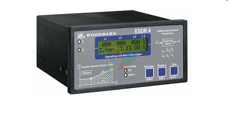
The ESDR 4 is a three-phase current differential protection relay for generators and motors (protected object).
The currents flowing in the individual lines are each measured using a current transformer on both sides of the
protected object. They form the protection area boundary or zone. All two or three-phase short circuits and line
to-earth faults within this protection area are detected by the ESDR 4 as fault currents which initiate tripping.The
unit does not trip if fault currents occur outside the protection zone. In this way, a selective protection is guaran
teed.
The unit monitors six (6) measured currents via isolated inputs. The unit calculates internally the restraint current
(Is) and the differential current (Id) separately for each phase. The actual values of the calculated parameters (Dif
ferential current Id und Restraint current IS) are shown on the display either as absolute values or as a percentage
of the generator rated current (selectable in locked input mode).
Theoretically the currents Ia and Ib are equal, both in fault-free operation and outside the protection zone (Figure
4-1-a).The difference is zero and the differential protection does not initiate. However, in practice current differ
entials do occur (= spurious currents), even in fault-free operation. They result, for example, from summation or
phase angle errors in the CTs, which are influenced by deviating burden values. These spurious currents remain
small inside the operating range, but increase with increasing load and are especially high when one or more CTs
become saturated (e.g. in the case of an external short circuit). In order to prevent a tripping of the relay due to
spurious currents, the trigger threshold is not held statically constant but increases in relation to the restraint cur
rent Is. Spurious currents need to be taken into account when adjusting the trip characteristic.
When a fault occurs inside the protection area (Figure 4-1-b), unequal currents flow in the CTs, which result in a
current differential. If this exceeds the differential protection threshold, the relay will trip.
Monitoring of the Differential Current
The monitoring of the differential current is carried out in two stages..
The first monitoring level serves as a warning and can be enabled or disabled. Should the adjustable warning
characteristic be exceeded, a text appears in the display and a relay contact is enabled. The pick-up time and the
dropout delay of the relay output are adjustable. The warning stage of the monitoring is auto-resetting.
The second stage of monitoring (main stage) serves to initiate tripping. In contrast to the first stage, it offers the
possibility to monitor the overstepping of an adjustable tripping characteristic (Id < In) and additionally, a fixed
tripping-threshold of 100%, relative to the generator rated current (Id > In). The trigger-delay for each limit value
may be independently adjusted, thus allowing a shorter triggering time at higher differential currents. When one
or both tripping characteristics are exceeded, a text display is initiated and two relay contacts are energized. The
tripping characteristics possess a 2% hysterisis relative to the generator rated current. .
The signal relay is only automatically reset if the function "automatic reset relay" in the Entry field on the screen
is configured to "on". Otherwise, the resetting is carried out by pressing the "Clear" button on the front of the
unit or via the discrete input terminal 18 "reset".
The two monitoring levels can also be used to change the characteristics of the control function (stage 1: small
value and a long time; stage 2: high value and a short time)
Tripping Characteristic
The following figure shows the tripping and warning characteristics (with sample values for X12. Y1.and Y2). It
represents the tripping and warning thresholds (Y) relative to the restraint current (X) The positions of the corner
points are determined by the coordinates P (X12/Y2) and P (X12/Y1). The selection of these positions is depend
ent on the generator being protected. The following gives the ranges of tripping and warning thresholds:
IS / IN
IS / IN
IS / IN
0 to X12
X12 to 5 × IN
> 5 × IN
The threshold Id is independent of the restraint current..
The threshold Id is dependent on the restraint current. A change of 100% in the
restraint current causes an increase of 10% in the tripping threshold.
The threshold Id stays constant at 85%.
Different characteristics can be chosen for the first and second monitoring levels, whereby the horizontal position
(X-coordinate) is valid for both stages. The vertical position (Y-coordinate) can be chosen separately for each
monitoring level. This results in a fixed difference in thresholds of the first and second monitioring levels for
each restraint current Is.
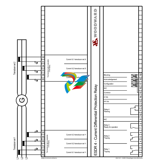
Control Inputs
Configuration
Terminal 17
Acknowledgement
Terminal 18
Blocking
Terminal19
Relays
Tripping (relay 1)
Terminals 1/2/3
Tripping (relay 2)
Terminals 4/5/6
Warning (relay 4)
Terminals 11/12/13
Ready for operation
(relay 3)
Terminals 7/8
When this input is energized, the unit locks into Configuration mode and stays in this
-
SHINKAWA MODEL VM-5Z5,6,7 POWER SUPPLY UNIT
-
SHINKAWA MODEL VM-5Y1,2,3 RELAY MODULE UNIT
-
SHINKAWA MODEL VM-5P3 PHASE MARKER UNIT
-
SHINKAWA MODEL VM-53 DUAL COMMUNICATION UNIT
-
SHINKAWA MODEL VM-52 BOTTOM HOLD MONITOR
-
SHINKAWA MODEL VM-51 ROD DROP MONITOR
-
SHINKAWA MODEL VM-5R TACHOMETER
-
SHINKAWA MODEL VM-5S DUAL TACHOMETER
-
SHINKAWA MODEL VM-5A DUAL VALVE
-
SHINKAWA MODEL VM-5E DUAL CASE
-
SHINKAWA MODEL VM-5L COMPLEMENTARY INPUT
-
SHINKAWA MODEL VM-5N RAMP DIFFERENTIAL
-
SHINKAWA MODEL VM-5D DUAL DIFFERENTIAL
-
SHINKAWA MODEL VM-5T DUAL THRUST MONITOR
-
SHINKAWA MODEL VM-5C ECCENTRICITY MONITOR
-
SHINKAWA MODEL VM-5C ECCENTRICITY MONITOR
-
SHINKAWA MODEL VM-5M DUAL PATH MONITOR
-
SHINKAWA MODEL VM-5B DUAL ACCELERATION MONITOR
-
SHINKAWA MODEL VM-5B DUAL ACCELERATION MONITOR
-
SHINKAWA MODEL VM-5U DUAL SEISMIC MONITOR
-
SHINKAWA MODEL VM-55 VIBRATION MONITOR
-
SHINKAWA VM-742B1-5 VIBRATION MONITORING SYSTEM CARD
-
Shinkawa PSP-17B P-24-64A P-24-64B Circuit Board Module
-
SHINKAWA MGP-67 PCB
-
Shinkawa JBP-278 P-22-48A-1 P-22-48B-1 Circuit Board Module
-
Shinkawa VM-721B 18-CHANNEL RELAY MODULE
-
Shinkawa FRP-337 P-26-54A P-26-54B Circuit Board Module
-
Shinkawa WKN-142K2-2 Vibration Transmitter
-
SHINKAWA VL-202A08L-1012 Rotor Position Monitor Probe Sensor
-
Shinkawa CPP-128 P-26-74A P-26-74B Circuit Board Module
-
Honeywell 51402755-100 PROCESSOR CARD
-
Honeywell 51107595-100 Power
-
HONEYWELL 51304544-100 Control Board
-
HONEYWELL 51109919-100 BOARD
-
HHoneywell 51204160-175 Digital Input Module
-
Honeywell 51304754-150 High Level Analog Input Module
-
HONEYWELL 51304690-100 DIGITAL INPUT CARD
-
Honeywell 51401635-150 COMM CONTROL
-
HONEYWELL 51204174-175 MC-TAOY 52 ANALOG OUTPUT BOARD
-
HONEYWELL 51400596-100
-
HONEYWELL 51401291-100 board card
-
HONEYWELL 51401642-150 I/O LINK MODULE
-
Honeywell LCN‑E Hub Power Supply 38500148‑300
-
Honeywell LCN‑E Hub redundant 38500143‑202 Twisted‑pair LCN
-
Honeywell LCN‑E Hub non‑redundant,38500143‑102
-
Honeywell Enhanced Micro‑TDC‑3000 System Unit MX‑DTAC01K2
-
Honeywell Enhanced Micro‑TDC‑3000 System Unit MX‑DTAB01K2
-
Honeywell Enhanced Micro‑TDC‑3000 System Unit MT11‑520
-
Honeywell STI‑CE Smart Transmitter Interface 51304516‑150
-
Honeywell STI Smart Transmitter Interface 51304516‑100 MC‑PSTX02
-
Honeywell ulse Counter IOP 51304386‑100 MU‑PPIX02
-
Honeywell DO Digital Output IOP‑CE 51304487‑150 CE version
-
Honeywell DO Digital Output IOP 51304487‑100 MC‑PDOX02
-
Honeywell TDC‑3000 SOE DI IOP,51402625-175 MC‑PDIS12
-
Honeywell TDC‑3000 DI Digital Input IOP‑CE 51304485‑150
-
Honeywell TDC‑3000 DI Digital Input IOP 51304485‑100 MC‑PDIX02
-
Honeywell TDC‑3000 AO Analog Output IOP 51304757‑100 MU‑PAOX02
-
Honeywell TDC‑3000 TC Thermocouple IOP 51304756‑100 MU‑TAMT03
-
Honeywell TDC‑3000 51304755‑100 MU‑TAMR03
-
Honeywell TDC‑3000 LLAI Multiplex AI IOP,51304362‑150
-
Honeywell TDC‑3000 HLAI Analog Input IOP‑CE, 51304363‑150
-
Honeywell TDC‑3000 HLAI Analog Input IOP,51304363‑100.4‑20mA
-
Honeywell TDC‑3000 HPM Power Supply,51401731‑100
-
Honeywell TDC‑3000 Standard 1986.HPM High‑Performance PM CPU,51402362‑100
-
Honeywell TDC‑3000 APM Advanced Process Manager CPU,51304459‑100
-
Honeywell TDC‑3000 Standard 1986.PM Process Manager CPU,51304362‑100
-
Honeywell TDC‑3000 NIM Network Interface Module,51304481‑200
-
Honeywell TDC‑3000 NIM Network Interface Module 51304481‑100
-
Honeywell TDC‑3000 BASIC,LCN Terminator Resistor,30732052‑001.Coaxial
-
Honeywell TDC‑3000 BASIC,Hiway Coupler,30753732‑001
-
Honeywell TDC‑3000 BASIC,LEPIU Low‑Energy PIU,4DP7APCFA309
-
Honeywell TDC‑3000 BASIC,HLPIU High‑Level PIU,4DP7APCFA106
-
Honeywell TDC‑3000 BASIC,Multifunction Controller(TDC‑2000 DHW),4DP7MFA103
-
Honeywell TDC‑3000 BASIC,Extended Controller(TDC‑2000 DHW),4DP7AXA102
-
Honeywell TDC‑3000 BASIC,Basic Controller(TDC‑2000 DHW),4DP7BBA101
-
Honeywell 51305508‑100 TDC‑3000 BASIC,XLCNE2 LCN Extender
-
Honeywell TDC‑3000 BASIC,E‑PLCG PLC Gateway,51400997‑200
-
Honeywell TDC‑3000 BASIC,PLNM Plant Network Module,51401163‑100
-
Honeywell TDC‑3000 BASIC,CG Computer Gateway,80360206‑001
-
Honeywell TDC‑3000 BASIC,HG High‑Speed Gateway,51304526‑100
-
Honeywell TDC‑3000 BASIC,HM History Module,51191596‑200
-
Honeywell TDC‑3000 BASIC,HM History Module,51191596‑100
-
Honeywell TDC‑3000 BASIC,AM Application Module CPU,51401551‑800.K2LCN‑8
-
Honeywell TDC‑3000 BASIC,AM Application Module CPU,51401551‑600.K2LCN‑6
-
Honeywell TDC‑3000 BASIC,AM Application Module CPU,51401551‑400,K2LCN‑4
-
Honeywell TDC‑3000 BASIC,AM Application Module CPU,51401551‑300.K2LCN‑3
-
Honeywell TDC‑3000 BASIC,AM Application Module CPU,51401551‑200,K2LCN‑2
-
Honeywell TDC‑3000 BASIC,US Universal Station CPU,51401288‑200
-
Honeywell TDC‑3000 BASIC,US Universal Station CPU,51401288‑100
-
SHINKAWA VM-21P1 Signal Conditioner 0-50MM 24VDC
-
Shinkawa RiverNew Vibration Transducer VK202 Series
-
Shinkawa Electric VM-3E2 Vibration Monitor Module
-
Shinkawa JBP-47 P-22-48A-1 / P-22-48B-1 Circuit Board Module
-
Shinkawa MODEL VM-5K DUAL VIBRATION MONITOR
-
Shinkawa CMU-15A (CMU15A) Industrial Camera Controller
-
Shinkawa CMU-13A CMU13A Industrial Camera Controller
-
Shinkawa EFU-10 (EFU10) Spark Generator Unit
-
Shinkawa UTC-1000 ZUP-02C Board
-
Shinkawa MDP-89 MDP89 P-24-674A P-24-674B Circuit Board Module
-
Shinkawa CB-1011005001 Signal Cable Assembly
-
SHINKAWA VL-202A08L-1002 Sensor VL-08020L01 Probe Cable F84N1695
-
Shinkawa VK-202A2 Driver & VL-202A08L-1A72 Proximity Sensor Probe
-
SHINKAWA VM-703B VIBRATION MONITORING SYSTEM CARD 2R05-002-P001C
-
Shinkawa BH-150-03 Signal Conditioner / Preamplifier Unit
-
Shinkawa BH-150 Signal Conditioner / Preamplifier Unit
-
Shinkawa Electric VM-3D2 Thrust Monitor Module
-
Shinkawa LCU-37 Monitoring module
-
Shinkawa LCU-44B-06 Local Control Unit Module
-
ABB 3BHE039724R2643 PPD513 high-performance programmable controller module
-
Samsung SSAS21-RTD Resistance Temperature Detector Input Module
-
Samsung SSAS21-AI Analog Input Module
-
Samsung SSAS21-DO Digital Output Module
-
Samsung SSAS21-DI Digital Input Module
-
Samsung SSAS21-CPU Central Processing Unit Module
-
Samsung SMTB-RTD RTD/TC Terminal Board
-
Samsung SMTB-AI Analog Input/Output Terminal Board
-
Samsung SMTB-DO Digital Output Terminal Board
-
Samsung SMTB-DI Digital Input Terminal Board
-
SAMSUNG SMBK-12 IOU Rack Backplane
-
SAMSUNG SMBK-08 IOU Rack Backplane
-
SAMSUNG SMPS-08 Rack Power Module
-
SAMSUNG SMCOM-08 Communication Expansion Card
-
SAMSUNG SMPI-8 Pulse Count Input Module
-
SAMSUNG SMTC-8 Thermocouple Input Module
-
SAMSUNG SMAOC-12 Analog Output Module (12CH)
-
SAMSUNG SMAOC-8 Analog Output Module (8CH)
-
SAMSUNG SMAIC-12 Analog Current Input Module (12CH)
-
SAMSUNG SMRTD-8 RTD Pt100 Temperature Input Module (8CH)

Add: High-tech Software Park, Xiamen City, Fujian Province
Mobile: +86-17750019513(WhatsApp)
Email: yy4291644@gmail.com
Website: https://www.abb-sis.com
.jpg)
.jpg)
.jpg)
.jpg)
.jpg)
.jpg)

-
SHINKAWA MODEL VM-5Z5,6,7 POWER SUPPLY UNIT
-
SHINKAWA MODEL VM-5Y1,2,3 RELAY MODULE UNIT
-
SHINKAWA MODEL VM-5P3 PHASE MARKER UNIT
-
SHINKAWA MODEL VM-53 DUAL COMMUNICATION UNIT
-
SHINKAWA MODEL VM-52 BOTTOM HOLD MONITOR
