

Woodward ESDR 4 Current Differential Protection Relay
mode until the terminal is de-energized.
If this input remains energized for at least 1 s, the faults detected in monitoring
level 2 are reset. This means that the relays will be de-energized and the text display
will be deleted from the screen as long as the monitored currents are not exceeding
the configured threshold level.
When this input is energized, the differential protection is disabled.This means that
the differential current is not monitored, no relay can be enabled and no text is dis
played.
This relay becomes enabled when the unit detects threshold limit 2 (main stage) has
been exceeded. The configured differential current characteristics and delay time will
determine how relay 1 functions.
This relay becomes enabled when the unit detects threshold limit 2 (main stage) has
been exceeded. The configured differential current characteristics and delay time will
determine how relay 2 functions.
This relay becomes enabled when the unit detects threshold limit 1 has been ex
ceeded. The configured differential current characteristics and delay time will deter
mine how relay 4 functions.
This relay is enabled when the unit is operational and the differential current is being
monitored. The relay becomes disabled if the monitoring is deactivated through any
of the following reasons:
• the internal self-monitoring has detected a malfunction of the unit. A correct func
tioning of the unit cannot be guaranteed and corrective action may be necessary.
• the set values for parameter "CT-ratio" or parameter "Generator Current" are out
side the permissible limits (see page 19).
• the digital input "Blocking" is energized.
• the parameter "Monitoring" is configured to "Off".
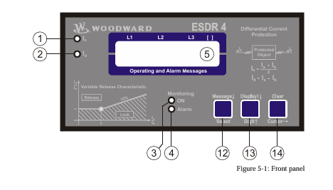
When in configuration mode (simultaneous pressing of "Digit↑" and "Cursor→"), the configuration screen can
be advanced by pressing the "Select" button. Should there be no entry, parameter change or other action for 60
seconds, the unit will automatically revert into Automatic mode.
During the configuration mode, the monitoring function is still active. This means inevitably, that while adjusting
parameters during operation, it is possible to cause a tripping of the relay.
adjust settings
[press "SELECT"]
Configuration mode "Select" button
Pressing the "Select" key activates the configuration mode, and the following pa
rameters can be enabled or changed within the given limits. Please you note that as
you advance through the configuration screens, by configuring some parameters as
"ON", additional screens must be configured relating to that parameter. If the pa
rameter is configured as "OFF", the additional screens will be disabled and not dis
played.
Software version
Software version
Displays the software version.
SPRACHE/LANGUAGE ----------------
Language selection english/german
The screens can be displayed in German or English.
curr. transform.
ratio 0000/x
CT-Ratio Selection 10 to 6.000/{x} A
The Ratio of the CTs being used is entered here. The CTs should be selected so that
in fault-free operation at generator rated current, at least 60 % of nominal current
flows in the CT-secondary. Failure to use properly a sized CT-Ratio leads to loss of
resolution and inaccuracies in the monitoring functions.
generator nomin.
current 0000A
Generator rated current 5 to 6.000 A
This value is used as reference value for the calculation and display of restraint cur
rent and differential current. The entered value of generator current must be at least
60% of the nominal current of the CT and must not exceed the entered value of CT
nominal current.
Example CT-Ratio 500/5 A
Range of Generator rated current 300 A to 500 A.
If the nominal value is less than 50% of the transformer ratio, the message "Wrong
Entry" will be displayed on the screen in Automatic mode and the unit will de
activate monitoring functions (the Monitoring LED goes out).
automatic reset
relay ON
Automatic reset of the relay ON/OFF
Applies only to monitoring level 2 (tripping).
Monitoring level 1 (warning) always Auto-resets.
ON................The relays de-energize automatically when the fault is no longer pre
sent. The screen input "Automatic reset of error text" determines
what happens to the Alarm-text in the display.
OFF..............The relays remain energized until they are reset.
monitoring
ON
Monitoring ON/OFF
ON................Monitoring of the differential current is active and the follow
ingscreens of this option are displayed.
OFF..............The monitoring is de-activated and the following screens are not dis
played.
release limit
Is/In X=000%
Trigger Value IS/IN (X12) 50 to 300 %
Definition of the threshold characteristic for the monitoring of levels 1 and 2.
This value determines the horizontal position (X12-coordinates of points
P [X12/Y1] and P [X2/Y2]) of the corner points of the Warning and Tripping char
acteristics.
release limit
Id/In Y=000%
Limit valueId
This value determines the vertical position (Y2-coordinate) of the corner point
P [X12/Y2] of the tripping characteristic (monitoring level2).
-
SHINKAWA MODEL VM-5Z5,6,7 POWER SUPPLY UNIT
-
SHINKAWA MODEL VM-5Y1,2,3 RELAY MODULE UNIT
-
SHINKAWA MODEL VM-5P3 PHASE MARKER UNIT
-
SHINKAWA MODEL VM-53 DUAL COMMUNICATION UNIT
-
SHINKAWA MODEL VM-52 BOTTOM HOLD MONITOR
-
SHINKAWA MODEL VM-51 ROD DROP MONITOR
-
SHINKAWA MODEL VM-5R TACHOMETER
-
SHINKAWA MODEL VM-5S DUAL TACHOMETER
-
SHINKAWA MODEL VM-5A DUAL VALVE
-
SHINKAWA MODEL VM-5E DUAL CASE
-
SHINKAWA MODEL VM-5L COMPLEMENTARY INPUT
-
SHINKAWA MODEL VM-5N RAMP DIFFERENTIAL
-
SHINKAWA MODEL VM-5D DUAL DIFFERENTIAL
-
SHINKAWA MODEL VM-5T DUAL THRUST MONITOR
-
SHINKAWA MODEL VM-5C ECCENTRICITY MONITOR
-
SHINKAWA MODEL VM-5C ECCENTRICITY MONITOR
-
SHINKAWA MODEL VM-5M DUAL PATH MONITOR
-
SHINKAWA MODEL VM-5B DUAL ACCELERATION MONITOR
-
SHINKAWA MODEL VM-5B DUAL ACCELERATION MONITOR
-
SHINKAWA MODEL VM-5U DUAL SEISMIC MONITOR
-
SHINKAWA MODEL VM-55 VIBRATION MONITOR
-
SHINKAWA VM-742B1-5 VIBRATION MONITORING SYSTEM CARD
-
Shinkawa PSP-17B P-24-64A P-24-64B Circuit Board Module
-
SHINKAWA MGP-67 PCB
-
Shinkawa JBP-278 P-22-48A-1 P-22-48B-1 Circuit Board Module
-
Shinkawa VM-721B 18-CHANNEL RELAY MODULE
-
Shinkawa FRP-337 P-26-54A P-26-54B Circuit Board Module
-
Shinkawa WKN-142K2-2 Vibration Transmitter
-
SHINKAWA VL-202A08L-1012 Rotor Position Monitor Probe Sensor
-
Shinkawa CPP-128 P-26-74A P-26-74B Circuit Board Module
-
Honeywell 51402755-100 PROCESSOR CARD
-
Honeywell 51107595-100 Power
-
HONEYWELL 51304544-100 Control Board
-
HONEYWELL 51109919-100 BOARD
-
HHoneywell 51204160-175 Digital Input Module
-
Honeywell 51304754-150 High Level Analog Input Module
-
HONEYWELL 51304690-100 DIGITAL INPUT CARD
-
Honeywell 51401635-150 COMM CONTROL
-
HONEYWELL 51204174-175 MC-TAOY 52 ANALOG OUTPUT BOARD
-
HONEYWELL 51400596-100
-
HONEYWELL 51401291-100 board card
-
HONEYWELL 51401642-150 I/O LINK MODULE
-
Honeywell LCN‑E Hub Power Supply 38500148‑300
-
Honeywell LCN‑E Hub redundant 38500143‑202 Twisted‑pair LCN
-
Honeywell LCN‑E Hub non‑redundant,38500143‑102
-
Honeywell Enhanced Micro‑TDC‑3000 System Unit MX‑DTAC01K2
-
Honeywell Enhanced Micro‑TDC‑3000 System Unit MX‑DTAB01K2
-
Honeywell Enhanced Micro‑TDC‑3000 System Unit MT11‑520
-
Honeywell STI‑CE Smart Transmitter Interface 51304516‑150
-
Honeywell STI Smart Transmitter Interface 51304516‑100 MC‑PSTX02
-
Honeywell ulse Counter IOP 51304386‑100 MU‑PPIX02
-
Honeywell DO Digital Output IOP‑CE 51304487‑150 CE version
-
Honeywell DO Digital Output IOP 51304487‑100 MC‑PDOX02
-
Honeywell TDC‑3000 SOE DI IOP,51402625-175 MC‑PDIS12
-
Honeywell TDC‑3000 DI Digital Input IOP‑CE 51304485‑150
-
Honeywell TDC‑3000 DI Digital Input IOP 51304485‑100 MC‑PDIX02
-
Honeywell TDC‑3000 AO Analog Output IOP 51304757‑100 MU‑PAOX02
-
Honeywell TDC‑3000 TC Thermocouple IOP 51304756‑100 MU‑TAMT03
-
Honeywell TDC‑3000 51304755‑100 MU‑TAMR03
-
Honeywell TDC‑3000 LLAI Multiplex AI IOP,51304362‑150
-
Honeywell TDC‑3000 HLAI Analog Input IOP‑CE, 51304363‑150
-
Honeywell TDC‑3000 HLAI Analog Input IOP,51304363‑100.4‑20mA
-
Honeywell TDC‑3000 HPM Power Supply,51401731‑100
-
Honeywell TDC‑3000 Standard 1986.HPM High‑Performance PM CPU,51402362‑100
-
Honeywell TDC‑3000 APM Advanced Process Manager CPU,51304459‑100
-
Honeywell TDC‑3000 Standard 1986.PM Process Manager CPU,51304362‑100
-
Honeywell TDC‑3000 NIM Network Interface Module,51304481‑200
-
Honeywell TDC‑3000 NIM Network Interface Module 51304481‑100
-
Honeywell TDC‑3000 BASIC,LCN Terminator Resistor,30732052‑001.Coaxial
-
Honeywell TDC‑3000 BASIC,Hiway Coupler,30753732‑001
-
Honeywell TDC‑3000 BASIC,LEPIU Low‑Energy PIU,4DP7APCFA309
-
Honeywell TDC‑3000 BASIC,HLPIU High‑Level PIU,4DP7APCFA106
-
Honeywell TDC‑3000 BASIC,Multifunction Controller(TDC‑2000 DHW),4DP7MFA103
-
Honeywell TDC‑3000 BASIC,Extended Controller(TDC‑2000 DHW),4DP7AXA102
-
Honeywell TDC‑3000 BASIC,Basic Controller(TDC‑2000 DHW),4DP7BBA101
-
Honeywell 51305508‑100 TDC‑3000 BASIC,XLCNE2 LCN Extender
-
Honeywell TDC‑3000 BASIC,E‑PLCG PLC Gateway,51400997‑200
-
Honeywell TDC‑3000 BASIC,PLNM Plant Network Module,51401163‑100
-
Honeywell TDC‑3000 BASIC,CG Computer Gateway,80360206‑001
-
Honeywell TDC‑3000 BASIC,HG High‑Speed Gateway,51304526‑100
-
Honeywell TDC‑3000 BASIC,HM History Module,51191596‑200
-
Honeywell TDC‑3000 BASIC,HM History Module,51191596‑100
-
Honeywell TDC‑3000 BASIC,AM Application Module CPU,51401551‑800.K2LCN‑8
-
Honeywell TDC‑3000 BASIC,AM Application Module CPU,51401551‑600.K2LCN‑6
-
Honeywell TDC‑3000 BASIC,AM Application Module CPU,51401551‑400,K2LCN‑4
-
Honeywell TDC‑3000 BASIC,AM Application Module CPU,51401551‑300.K2LCN‑3
-
Honeywell TDC‑3000 BASIC,AM Application Module CPU,51401551‑200,K2LCN‑2
-
Honeywell TDC‑3000 BASIC,US Universal Station CPU,51401288‑200
-
Honeywell TDC‑3000 BASIC,US Universal Station CPU,51401288‑100
-
SHINKAWA VM-21P1 Signal Conditioner 0-50MM 24VDC
-
Shinkawa RiverNew Vibration Transducer VK202 Series
-
Shinkawa Electric VM-3E2 Vibration Monitor Module
-
Shinkawa JBP-47 P-22-48A-1 / P-22-48B-1 Circuit Board Module
-
Shinkawa MODEL VM-5K DUAL VIBRATION MONITOR
-
Shinkawa CMU-15A (CMU15A) Industrial Camera Controller
-
Shinkawa CMU-13A CMU13A Industrial Camera Controller
-
Shinkawa EFU-10 (EFU10) Spark Generator Unit
-
Shinkawa UTC-1000 ZUP-02C Board
-
Shinkawa MDP-89 MDP89 P-24-674A P-24-674B Circuit Board Module
-
Shinkawa CB-1011005001 Signal Cable Assembly
-
SHINKAWA VL-202A08L-1002 Sensor VL-08020L01 Probe Cable F84N1695
-
Shinkawa VK-202A2 Driver & VL-202A08L-1A72 Proximity Sensor Probe
-
SHINKAWA VM-703B VIBRATION MONITORING SYSTEM CARD 2R05-002-P001C
-
Shinkawa BH-150-03 Signal Conditioner / Preamplifier Unit
-
Shinkawa BH-150 Signal Conditioner / Preamplifier Unit
-
Shinkawa Electric VM-3D2 Thrust Monitor Module
-
Shinkawa LCU-37 Monitoring module
-
Shinkawa LCU-44B-06 Local Control Unit Module
-
ABB 3BHE039724R2643 PPD513 high-performance programmable controller module
-
Samsung SSAS21-RTD Resistance Temperature Detector Input Module
-
Samsung SSAS21-AI Analog Input Module
-
Samsung SSAS21-DO Digital Output Module
-
Samsung SSAS21-DI Digital Input Module
-
Samsung SSAS21-CPU Central Processing Unit Module
-
Samsung SMTB-RTD RTD/TC Terminal Board
-
Samsung SMTB-AI Analog Input/Output Terminal Board
-
Samsung SMTB-DO Digital Output Terminal Board
-
Samsung SMTB-DI Digital Input Terminal Board
-
SAMSUNG SMBK-12 IOU Rack Backplane
-
SAMSUNG SMBK-08 IOU Rack Backplane
-
SAMSUNG SMPS-08 Rack Power Module
-
SAMSUNG SMCOM-08 Communication Expansion Card
-
SAMSUNG SMPI-8 Pulse Count Input Module
-
SAMSUNG SMTC-8 Thermocouple Input Module
-
SAMSUNG SMAOC-12 Analog Output Module (12CH)
-
SAMSUNG SMAOC-8 Analog Output Module (8CH)
-
SAMSUNG SMAIC-12 Analog Current Input Module (12CH)
-
SAMSUNG SMRTD-8 RTD Pt100 Temperature Input Module (8CH)

Add: High-tech Software Park, Xiamen City, Fujian Province
Mobile: +86-17750019513(WhatsApp)
Email: yy4291644@gmail.com
Website: https://www.abb-sis.com
.jpg)
.jpg)
.jpg)
.jpg)
.jpg)
.jpg)

-
SHINKAWA MODEL VM-5Z5,6,7 POWER SUPPLY UNIT
-
SHINKAWA MODEL VM-5Y1,2,3 RELAY MODULE UNIT
-
SHINKAWA MODEL VM-5P3 PHASE MARKER UNIT
-
SHINKAWA MODEL VM-53 DUAL COMMUNICATION UNIT
-
SHINKAWA MODEL VM-52 BOTTOM HOLD MONITOR
