

Woodward easYgen-400 Operation Manual Genset Control
well as exploitation and/or communication of the content, are not permitted without a
written declaration of release by Woodward GmbH.
Actions to the contrary will entitle us to claim compensation for damages. We expressly
reserve the right to raise any further accessory claims
1.3
Service And Warranty
Opening the device will nullify any warranty
Any such unauthorized modifications
•
• constitute "misuse" and/or "negligence" as per the product warranty
•
• thereby exclude warranty coverage for any resulting damage, and
•
• invalidate product certifications or listings.
Our Customer Service is available for technical information. Please see page 2 for contact
details.
In addition, our employees are interested in any new information and experiences that
arise from usage and could be valuable for improving our products.
1.4
1.4.1
Safety
Intended Use
The easYgen unit has been designed and constructed solely for the intended use
described in this Operation Manual and – with even more details – in the Technical
Manual.
•
• Intended use requires operation of the control unit within the range outlined in the
written specifications.
Steps to be taken for commissioning are outlined in the Technical Manual. •
• Intended use includes compliance with all instructions and safety notes presented in •
this manual.
•Any use which exceeds or differs from the intended use shall be considered improper •
use.
•No claims for any kind for damage will be considered if such claims result from •
improper use.
1.4.2 Personnel
This manual specifies the personnel qualifications required for the different areas of work,
listed below:
•Well trained for electrical installations. •
•Aware of the local safety regulations. •
•Experienced in working with electronic measuring and control devices. •
•Allowed to manage the controlled (engine/generator) system. •
The workforce must only consist of persons who can be expected to carry out their work
reliably. Persons with impaired reactions due to, for example, the consumption of drugs,
alcohol, or medication are prohibited.
When selecting personnel, the age-related and occupation-related regulations governing
the operating location must be observed
System Overview
General notes
The easYgen is a stand-alone genset controller with measuring, monitoring, and breaker
control functionality. It comes with an easily mountable plastic housing covering a
thoroughly tested electronic-electrical system.
Display and buttons of the HMI offer access to states and values, as well as access to the
application. Password protection enables the assignment of multiple operation access
levels. Remote access, monitoring, visualization, and configuration are possible via
integrated interfaces. Communication between easYgens using PLC control or as a
network member offers an enhanced system management range; additionally supported
by easy to implement accessories
2.1
2.2
HMI Status Screens
HMI displays the following status screens:
•
• Status (home)
•
• Generator
•
• Load
•
• Engine 1
•
• Engine 2
•
• Status
•
• Alarm
•
• home screen etc.
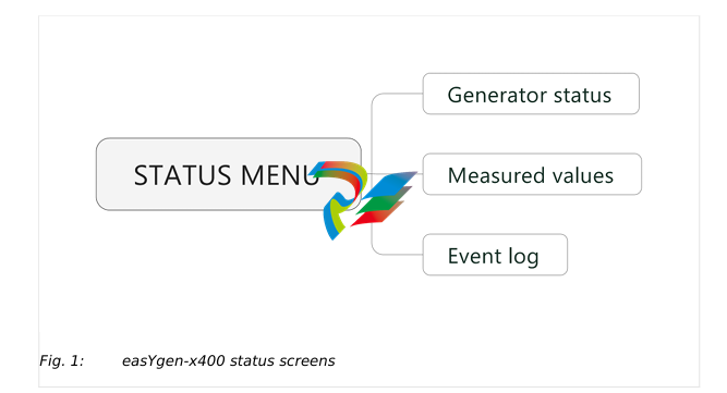
ToolKit-SC Status Screens
General notes
ToolKit-SC lets you access status information via the following screens
Items Parameters Description
Engine info Engine speed, Battery volt, Charger volt D+
Sensor info Engine temp, Oil pressure, Fuel level Selection of ECU
data via J1939.
More info Coolant pressure, Coolant level,Fuel pressure, Fuel
temp, Turbo pressure, Oil temp, Inlet temp, Fuel
consume, Exhaust temp, Total consume
Alarms Current Alarms and Warning Lists of current
alarms and
warnings
(Digital )Inputs 01 High temperature shutdown, 02 Low oil pressure
shutdown, 10 Start request in AUTO, 11 Fuel level
warning, 12 Coolant level warning
(Digital) Outputs 02 Stop solenoid, 03 Idle control, 05 Close GCB, 06
Fuel relay, Start relay
Accumulation (run) Time, Starts
Next maintenance
time
Time
Engine hours Time
Generator status Gen status
Module info will be moved to Event log page
Items Parameters Description
Electricity quantity
Mains-/
Generator L1. L2. L3. L1-2. L2-3. L3-1. L1Phase, L2Phase, L3Phase, Frequency
Current (A) L1. L2. L3
Active power (kW) L1. L2. L3. Total
Reactive power (kvar) L1. L2. L3. Total
Apparent power (kVA) L1. L2. L3. Total
Power factor L1. L2. L3. Avg
Ext. Analog Inputs
[PARAMETER / STATUS MENU / Ext. analog inputs]
Items Parameters Description
Expansion AIN24 {X} {X}: 1 or 2
Cylinder Temp {Y} (in °C and °F) {Y}: 1 or 22
Exhaust Temp {Z} (in °C and °F) {Z}: 1 or 2
Sensor {N} {N}: 15 or 24
Event Log and Version
[PARAMETER / STATUS MENU / Event log and version]
Items Parameters Description
Module Info Model, Hardware Version, Software Version, Issue Date
Event log Fixed view of:
No., Event type
Columns "move behind" visible part of the screen:
Event Item, Date, Time,
((Mains control is not supported by this model, so all "Mains" values
are"0":))
Mains Uab (V) / Ubc (V) / Uca (V), Mains Ua (V), Mains Ub (V), Mains
Uc (V), Mains f (Hz),
Gens Uab (V) ..., Gens Ua (V) ..., Gens f(Hz),
Current Ia (A) ...,
Power (kW),
Speed (r/min),
Temp. (°C),
Press. (kPa),
Volt. (V)
Event log report
table. Showss the
99 latest events
Icons Keys Description
STOP Auto/Manual mode: Stops running generator
-
Beckhoff CX5120-0160 CPU module,
-
Beckhoff CX5120-0150 CPU module
-
Beckhoff CX5120-0143 CPU module
-
Beckhoff CX5120-0142 CPU module
-
Beckhoff CX5120-0141 CPU module, Microsoft Windows 10 IoT Enterprise 2016 LTSB
-
Beckhoff CX5120-0140 CPU module
-
Beckhoff CX5120-0130 CPU module
-
Beckhoff CX5120-0123 CPU module
-
Beckhoff CX5120-0122 CPU module
-
Beckhoff CX5120-0120 CPU module
-
Beckhoff CX5120-0113 CPU module
-
Beckhoff CX5120-0112 CPU module
-
Beckhoff CX5120-0111 CPU module
-
Beckhoff CX5120-0110 CPU module
-
Beckhoff CX5120-0100 CPU module, no operating system
-
Beckhoff C6017-0040 | Fanless ultra-compact Industrial PC
-
Beckhoff C6017 | Fanless ultra-compact Industrial PC
-
Beckhoff C6015-0030 | Fanless ultra-compact Industrial PC
-
Beckhoff C6015-0040 | Fanless ultra-compact Industrial PC
-
Beckhoff C6015 | Fanless ultra-compact Industrial PC
-
Beckhoff CX2500-M510 | Fieldbus master module
-
Beckhoff CX2500-M310 | Fieldbus master module
-
Beckhoff CX2500-B510 | Fieldbus slave module
-
Beckhoff CX2500-B310 | Fieldbus slave module PROFIBUS for CX20xx, CX52x0. CX53x0. CX56x0
-
Beckhoff CX2500-0070 | USB 3.0 module for CX20xx, CX52xx, CX53x0. CX56x0
-
Beckhoff CX2500-0062 | 2.5 Gbit Ethernet module for CX20xx, CX52x0. CX53x0. CX56x0
-
Beckhoff CX2500-1061 | Power over Ethernet module for CX20xx, CX52x0. CX53x0. CX56x0
-
Beckhoff CX2500-1060 | Ethernet module for CX20xx, CX52x0. CX53x0. CX56x0
-
Beckhoff CX2500-0031 | Serial Interface RS485/RS422
-
Beckhoff CX2500-0030 | Serial Interface RS232 for CX20xx, CX52x0. CX53x0. CX56x0
-
Beckhoff CX5230-0195 CPU module
-
Beckhoff CX5230-0190 CPU module
-
Beckhoff CX5230-0175 CPU module,
-
Beckhoff CX5230-0170 CPU module
-
Beckhoff CX5230-0100 CPU module, no operating system, no TwinCAT
-
Beckhoff CU8130-0240 | UPS modul, battery-backed
-
Beckhoff CU8130-0120 | UPS module, battery-backed
-
Beckhoff CU8110-0120 | UPS module, capacitive
-
Beckhoff CU8110-0060 | UPS module, capacitive
-
Beckhoff CX5130-0195 CPU module
-
Beckhoff CX5130-0190 CPU module
-
Beckhoff CX5130-0185 CPU module
-
Beckhoff CX5130-0170 CPU module
-
Beckhoff CX5130-0163 CPU module, Microsoft Windows 10 IoT Enterprise 2019 LTSC, 32 bit
-
Beckhoff CX5130-0162 CPU module
-
Beckhoff CX5130-0161 CPU module
-
Beckhoff CX5130-0160 CPU module
-
Beckhoff CX5130-0155 CPU module
-
Beckhoff CX5130-0150 CPU module
-
Beckhoff CX5130-0143 CPU module
-
Beckhoff CX5130-0142 CPU module
-
Beckhoff CX5130-0140 CPU module
-
Beckhoff CX5130-0135 CPU module
-
Beckhoff CX5130-0130 CPU module
-
Beckhoff CX5130-0125 CPU module
-
Beckhoff CX5130-0123 CPU module
-
Beckhoff CX5130-0122 CPU module
-
Beckhoff CX5130-0121 CPU module
-
Beckhoff CX5130-0115 CPU module,
-
Beckhoff CX5130-0113 CPU module
-
Beckhoff CX5130-0112 CPU module
-
Beckhoff CX5130-0111 CPU module
-
Beckhoff CX5130-0110 CPU module, Microsoft Windows Embedded Compact 7. no TwinCAT
-
Beckhoff CX5130-0100 CPU module, no operating system, no TwinCAT
-
DEIF FAS-113DG Synchronisation & circuit breaker closing
-
DEIF FAS-115DG Synchronisation & circuit breaker closing
-
DEIF HAS-111DG Synchronisation & circuit breaker closing
-
DEIF LSU-122DG Load sharing, paralleling & operation
-
DEIF LSU-114DG Load sharing, paralleling & operation
-
DEIF LSU-113DG Load sharing, paralleling & operation
-
DEIF LSU-112DG Load sharing, paralleling & operation
-
DEIF RMF-112D Frequency relay
-
DEIF RMC-142D Current relay
-
DEIF RMC-132D Current relay
-
DEIF RMC-131D Current relay
-
DEIF RMC-122D Current relay
-
DEIF RMC-121D Current relay
-
DEIF RMC-111D Current relay
-
DEIF MVR-V211 Busbar Protection
-
DEIF MVR-T257 Transformer Differential Protection
-
DEIF MVR-T256 Transformer Differential Protection
-
DEIF MVR-T216 Transformer Differential Protection
-
DEIF MVR-T215 Transformer Protection
-
DEIF MVR-M257 Motor Differential Protection
-
DEIF MVR-M255 Motor Protection
-
DEIF MVR-M215 Motor Protection
-
DEIF MVR-M210 Motor Protection
-
DEIF MVR-G257 Generator Differential Protection
-
DEIF MVR-G215 Generator Protection
-
DEIF MVR-F255 Directional Feeder Protection
-
DEIF MVR-F215 Directional Feeder Protection
-
DEIF MVR-F210 Feeder Protection
-
DEIF MVR-F205 Directional Feeder Protection
-
DEIF MVR-F201 Basic Feeder Protection
-
DEIF MVR-200 series Medium Voltage Relay
-
DEIF MDR-2 Multi-differential relay
-
DEIF LMR-122D Loss of mains relay
-
DEIF LMR-111D Loss of mains relay
-
DEIF APU-4 Advanced G59 and G99 protection unit
-
DEIF iE 650 PLC - The most robust programmable automation controller available
-
DEIF iE 350 PLC - Programmable Automation PLC Controller
-
DEIF iE 250 PLC Versatile and modular intelligent energy PLC controller
-
DEIF PPM-3 EDG Protection and Power Management
-
DEIF AGC 3X 4198000234E AUTOMATIC GENSET CONTROLLER
-
SAUTER ASF123 Damper actuator with spring return
-
SAUTER ASF122 Damper actuator with spring return
-
SAUTER ASF113F122 Damper actuator with spring return
-
SAUTER ASF113F120 Damper actuator with spring return
-
SAUTER ASF112F122 Damper actuator with spring return
-
SAUTER ASF112F120 Damper actuator with spring return
-
SAUTER ASM 124/134 series - ASM134F130 Damper actuator
-
SAUTER ASM 124/134 series - ASM134SF132 Damper actuator
-
SAUTER ASM 124/134 series - ASM124SF132 Damper actuator
-
SAUTER ASM 124/134 series - ASM124F122 Damper actuator
-
SAUTER ASM 124/134 series - ASM124F120 Damper actuator
-
SAUTER Valve actuator ASM 105S/115S series ASM115SF152
-
SAUTER Valve actuator ASM 105S/115S series ASM105SF152
-
SAUTER Valve actuator ASM 105S/115S series ASM115SF132
-
SAUTER Valve actuator ASM 105/115 series ASM105SF132
-
SAUTER Valve actuator ASM 105/115 series ASM115F122
-
SAUTER Valve actuator ASM 105/115 series ASM115F120
-
SAUTER Valve actuator ASM 105/115 series ASM105F122
-
SAUTER Valve actuator ASM 105/115 series ASM105F120
-
SAUTER Valve actuator ASM 105/115 series ASM105F10
-
SAUTER AKF113S Rotating actuator AKF 112/113 series
-
SAUTER AKF113F122 Rotating actuator AKF 112/113 series
-
SAUTER AKF113F120 Rotating actuator AKF 112/113 series
-
SAUTER AKF112F122 Rotating actuator AKF 112/113 series

Add: High-tech Software Park, Xiamen City, Fujian Province
Mobile: +86-17750019513(WhatsApp)
Email: yy4291644@gmail.com
Website: https://www.abb-sis.com
.jpg)
.jpg)
.jpg)
.jpg)
.jpg)
.jpg)

-
Beckhoff CX5120-0160 CPU module,
-
Beckhoff CX5120-0150 CPU module
-
Beckhoff CX5120-0143 CPU module
-
Beckhoff CX5120-0142 CPU module
-
Beckhoff CX5120-0141 CPU module, Microsoft Windows 10 IoT Enterprise 2016 LTSB
