

Woodward easYgen-400 Operation Manual Genset Control
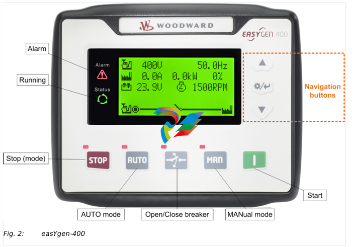
Stop mode: Resets alarm
Lamp test (press at least 3 seconds)
Notes
During stopping process, press this button again to stop generator
immediately.
I (START) MANual mode: Start genset
MAN (Manual Mode) Press this key and the controller enters into MAN mode
AUTO (Automatic Mode) Press this key and the controller enters into AUTO mode
Open/Close breaker Release breaker control in MAN mode.
The navigation button "Up/Increase" is used to close the GCB
3.2.1
3.3
Alarm Acknowledgment
General notes
The alarm acknowledge handling is valid for following alarm classes
•
• Shutdown
•
• Trip/Stop
•
• Trip
Mute Horn
Any new active alarm activates the horn and is made visible by the flashing Alarm LED.
After pressing the "Down/Decrease" button, the horn is deactivated and the Alarm LED
changes from flashing to constantly active and stays active as long as any alarm is
present. An additional active alarm reactivates the horn and the Alarm LED starts flashing
again.
Stop by alarm
The operation mode automatically changes to STOP if a stopping alarm is active
(»Shutdown« or »Trip/Stop«).
Acknowledge alarm
In case of alarm condition, pressing the STOP button will reset the alarm.
Operation Modes
General notes
The easYgen offers three operation modes:
•
• AUTO
•
• MANUAL (MAN)
•
• STOP
•
• ... and an internal (non) operating phase during the start of the device itself
The operation mode can be initiated – provided the current settings allow for this
function:
•
• directly by pressing the respective button on the front panel
•
• directly by click on the respective button on the ToolKit-SC remote screen
•
• via discrete inputs
•
• via interface
3.3.1
General notes
In operation mode AUTO, both genset and breaker are under easYgen control. The start
and stopping of the engine is managed automatically, along with opening/closing the
breaker.
•
• supply load by generator
•
• start the engine
•
• stop the engine
3.3.2
Operation Mode MANual
General notes
In operation mode MANual, both genset and breakers are independent of each other
under easYgen control.
The starting and stopping of the engine are managed using the same procedure as in
AUTO mode but without breaker control. Breakers can be opened and closed without
taking care of load or genset state!
3.3.3
Operation Mode STOP
General notes
In operation mode STOP, the breaker is open and the engine is not running.
3.4
3.4.1
START/STOP Operation
Start engine to supply load
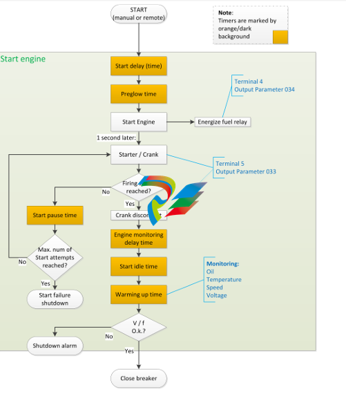
The AUTO Start procedure is going through sub procedures with own timers
3.5
Pressing
can stop the running generator as described above.
Transition Procedures
3.5.1
Disconnect during cranking
There are three conditions under control to abort the starting of the engine:
•
• speed sensor
•
• generator frequency
•
• engine oil pressure
They can be used separately or in combinations.
We recommend selecting all three at the same time: engine oil pressure together with
speed sensor, and generator frequency. This allows for an immediate separation of the
starter motor from the engine. Additionally, crank disconnect can be checked exactly.
When set to speed sensor, ensure that the number of flywheel teeth is the same as
setting.
5 Glossary and List of Abbreviations
CB Circuit Breaker
CT Current Transformer
DI Discrete Input
DO Discrete (Relay) Output
ECU Engine Control Unit
FMI Failure Mode Indicator
GCB Generator Circuit Breaker
GOV (speed) Governor; rpm regulator
HMI Human Machine Interface e.g., a front panel with display and
buttons for interaction
I Current
MCB Mains Circuit Breaker
MPU Magnetic Pickup Unit
N.C. Normally Closed (break) contact
N.O. Normally Open (make) contact
NC Neutral Contactor
OC Occurrence Count
Operation In (general) operation.
State when the genset is running according to the selected
mode, all parameters are in allowed values and ranges, and
without OPEN requests or alarms. Somehow "waiting for next
occurrence".
P Real power
P/N Part Number
PF Power Factor
PT Potential (Voltage) Transformer
Q Reactive power
S Apparent power
S/N Serial Number
SPN Suspect Parameter Number
V Voltage
Index
A
Alarms
Classes . . . . . . . . . . . . . . . . . . . . . . . . . . . . . . . . . . . . . . . . . . . . . . . . . . . . . . . . . . . . . . . . . . . . . . . . . . . . . . . . . . . . . . . . . . . . 25█
Shutdown Alarms . . . . . . . . . . . . . . . . . . . . . . . . . . . . . . . . . . . . . . . . . . . . . . . . . . . . . . . . . . . . . . . . . . . . . . . . . . . . . . . . . . . . . . . . . . . . 26█
C
Contact person . . . . . . . . . . . . . . . . . . . . . . . . . . . . . . . . . . . . . . . . . . . . . . . . . . . . . . . . . . . . . . . . . . . . . . . . . . . . . . . . . . . . . . . . . . . . 9█
Customer Service . . . . . . . . . . . . . . . . . . . . . . . . . . . . . . . . . . . . . . . . . . . . . . . . . . . . . . . . . . . . . . . . . . . . . . . . . . . . . . . . . . . . . . . . . . . . 9█
F
Functions . . . . . . . . . . . . . . . . . . . . . . . . . . . . . . . . . . . . . . . . . . . . . . . . . . . . . . . . . . . . . . . . . . . . . . . . . . . . . . . . . . . . . . . . . . . . 12█
I
Intended use . . . . . . . . . . . . . . . . . . . . . . . . . . . . . . . . . . . . . . . . . . . . . . . . . . . . . . . . . . . . . . . . . . . . . . . . . . . . . . . . . . . . . . . . . . . . 9█
-
Beckhoff CX5120-0160 CPU module,
-
Beckhoff CX5120-0150 CPU module
-
Beckhoff CX5120-0143 CPU module
-
Beckhoff CX5120-0142 CPU module
-
Beckhoff CX5120-0141 CPU module, Microsoft Windows 10 IoT Enterprise 2016 LTSB
-
Beckhoff CX5120-0140 CPU module
-
Beckhoff CX5120-0130 CPU module
-
Beckhoff CX5120-0123 CPU module
-
Beckhoff CX5120-0122 CPU module
-
Beckhoff CX5120-0120 CPU module
-
Beckhoff CX5120-0113 CPU module
-
Beckhoff CX5120-0112 CPU module
-
Beckhoff CX5120-0111 CPU module
-
Beckhoff CX5120-0110 CPU module
-
Beckhoff CX5120-0100 CPU module, no operating system
-
Beckhoff C6017-0040 | Fanless ultra-compact Industrial PC
-
Beckhoff C6017 | Fanless ultra-compact Industrial PC
-
Beckhoff C6015-0030 | Fanless ultra-compact Industrial PC
-
Beckhoff C6015-0040 | Fanless ultra-compact Industrial PC
-
Beckhoff C6015 | Fanless ultra-compact Industrial PC
-
Beckhoff CX2500-M510 | Fieldbus master module
-
Beckhoff CX2500-M310 | Fieldbus master module
-
Beckhoff CX2500-B510 | Fieldbus slave module
-
Beckhoff CX2500-B310 | Fieldbus slave module PROFIBUS for CX20xx, CX52x0. CX53x0. CX56x0
-
Beckhoff CX2500-0070 | USB 3.0 module for CX20xx, CX52xx, CX53x0. CX56x0
-
Beckhoff CX2500-0062 | 2.5 Gbit Ethernet module for CX20xx, CX52x0. CX53x0. CX56x0
-
Beckhoff CX2500-1061 | Power over Ethernet module for CX20xx, CX52x0. CX53x0. CX56x0
-
Beckhoff CX2500-1060 | Ethernet module for CX20xx, CX52x0. CX53x0. CX56x0
-
Beckhoff CX2500-0031 | Serial Interface RS485/RS422
-
Beckhoff CX2500-0030 | Serial Interface RS232 for CX20xx, CX52x0. CX53x0. CX56x0
-
Beckhoff CX5230-0195 CPU module
-
Beckhoff CX5230-0190 CPU module
-
Beckhoff CX5230-0175 CPU module,
-
Beckhoff CX5230-0170 CPU module
-
Beckhoff CX5230-0100 CPU module, no operating system, no TwinCAT
-
Beckhoff CU8130-0240 | UPS modul, battery-backed
-
Beckhoff CU8130-0120 | UPS module, battery-backed
-
Beckhoff CU8110-0120 | UPS module, capacitive
-
Beckhoff CU8110-0060 | UPS module, capacitive
-
Beckhoff CX5130-0195 CPU module
-
Beckhoff CX5130-0190 CPU module
-
Beckhoff CX5130-0185 CPU module
-
Beckhoff CX5130-0170 CPU module
-
Beckhoff CX5130-0163 CPU module, Microsoft Windows 10 IoT Enterprise 2019 LTSC, 32 bit
-
Beckhoff CX5130-0162 CPU module
-
Beckhoff CX5130-0161 CPU module
-
Beckhoff CX5130-0160 CPU module
-
Beckhoff CX5130-0155 CPU module
-
Beckhoff CX5130-0150 CPU module
-
Beckhoff CX5130-0143 CPU module
-
Beckhoff CX5130-0142 CPU module
-
Beckhoff CX5130-0140 CPU module
-
Beckhoff CX5130-0135 CPU module
-
Beckhoff CX5130-0130 CPU module
-
Beckhoff CX5130-0125 CPU module
-
Beckhoff CX5130-0123 CPU module
-
Beckhoff CX5130-0122 CPU module
-
Beckhoff CX5130-0121 CPU module
-
Beckhoff CX5130-0115 CPU module,
-
Beckhoff CX5130-0113 CPU module
-
Beckhoff CX5130-0112 CPU module
-
Beckhoff CX5130-0111 CPU module
-
Beckhoff CX5130-0110 CPU module, Microsoft Windows Embedded Compact 7. no TwinCAT
-
Beckhoff CX5130-0100 CPU module, no operating system, no TwinCAT
-
DEIF FAS-113DG Synchronisation & circuit breaker closing
-
DEIF FAS-115DG Synchronisation & circuit breaker closing
-
DEIF HAS-111DG Synchronisation & circuit breaker closing
-
DEIF LSU-122DG Load sharing, paralleling & operation
-
DEIF LSU-114DG Load sharing, paralleling & operation
-
DEIF LSU-113DG Load sharing, paralleling & operation
-
DEIF LSU-112DG Load sharing, paralleling & operation
-
DEIF RMF-112D Frequency relay
-
DEIF RMC-142D Current relay
-
DEIF RMC-132D Current relay
-
DEIF RMC-131D Current relay
-
DEIF RMC-122D Current relay
-
DEIF RMC-121D Current relay
-
DEIF RMC-111D Current relay
-
DEIF MVR-V211 Busbar Protection
-
DEIF MVR-T257 Transformer Differential Protection
-
DEIF MVR-T256 Transformer Differential Protection
-
DEIF MVR-T216 Transformer Differential Protection
-
DEIF MVR-T215 Transformer Protection
-
DEIF MVR-M257 Motor Differential Protection
-
DEIF MVR-M255 Motor Protection
-
DEIF MVR-M215 Motor Protection
-
DEIF MVR-M210 Motor Protection
-
DEIF MVR-G257 Generator Differential Protection
-
DEIF MVR-G215 Generator Protection
-
DEIF MVR-F255 Directional Feeder Protection
-
DEIF MVR-F215 Directional Feeder Protection
-
DEIF MVR-F210 Feeder Protection
-
DEIF MVR-F205 Directional Feeder Protection
-
DEIF MVR-F201 Basic Feeder Protection
-
DEIF MVR-200 series Medium Voltage Relay
-
DEIF MDR-2 Multi-differential relay
-
DEIF LMR-122D Loss of mains relay
-
DEIF LMR-111D Loss of mains relay
-
DEIF APU-4 Advanced G59 and G99 protection unit
-
DEIF iE 650 PLC - The most robust programmable automation controller available
-
DEIF iE 350 PLC - Programmable Automation PLC Controller
-
DEIF iE 250 PLC Versatile and modular intelligent energy PLC controller
-
DEIF PPM-3 EDG Protection and Power Management
-
DEIF AGC 3X 4198000234E AUTOMATIC GENSET CONTROLLER
-
SAUTER ASF123 Damper actuator with spring return
-
SAUTER ASF122 Damper actuator with spring return
-
SAUTER ASF113F122 Damper actuator with spring return
-
SAUTER ASF113F120 Damper actuator with spring return
-
SAUTER ASF112F122 Damper actuator with spring return
-
SAUTER ASF112F120 Damper actuator with spring return
-
SAUTER ASM 124/134 series - ASM134F130 Damper actuator
-
SAUTER ASM 124/134 series - ASM134SF132 Damper actuator
-
SAUTER ASM 124/134 series - ASM124SF132 Damper actuator
-
SAUTER ASM 124/134 series - ASM124F122 Damper actuator
-
SAUTER ASM 124/134 series - ASM124F120 Damper actuator
-
SAUTER Valve actuator ASM 105S/115S series ASM115SF152
-
SAUTER Valve actuator ASM 105S/115S series ASM105SF152
-
SAUTER Valve actuator ASM 105S/115S series ASM115SF132
-
SAUTER Valve actuator ASM 105/115 series ASM105SF132
-
SAUTER Valve actuator ASM 105/115 series ASM115F122
-
SAUTER Valve actuator ASM 105/115 series ASM115F120
-
SAUTER Valve actuator ASM 105/115 series ASM105F122
-
SAUTER Valve actuator ASM 105/115 series ASM105F120
-
SAUTER Valve actuator ASM 105/115 series ASM105F10
-
SAUTER AKF113S Rotating actuator AKF 112/113 series
-
SAUTER AKF113F122 Rotating actuator AKF 112/113 series
-
SAUTER AKF113F120 Rotating actuator AKF 112/113 series
-
SAUTER AKF112F122 Rotating actuator AKF 112/113 series

Add: High-tech Software Park, Xiamen City, Fujian Province
Mobile: +86-17750019513(WhatsApp)
Email: yy4291644@gmail.com
Website: https://www.abb-sis.com
.jpg)
.jpg)
.jpg)
.jpg)
.jpg)
.jpg)

-
Beckhoff CX5120-0160 CPU module,
-
Beckhoff CX5120-0150 CPU module
-
Beckhoff CX5120-0143 CPU module
-
Beckhoff CX5120-0142 CPU module
-
Beckhoff CX5120-0141 CPU module, Microsoft Windows 10 IoT Enterprise 2016 LTSB
